Ex Cable Gland Selection & Installation: Avoiding Common Pitfalls in Hazardous Zone 1/2 Applications
The integrity of electrical installations in oil and gas hazardous areas hinges on one critical component often overlooked: the cable gland. A single compromised seal or material mismatch can transform a cable entry point into an ignition source, with catastrophic consequences. In Zone 1 and 2 environments—where flammable gases or vapors may exist during normal operations or process upsets—the selection and installation of Ex-certified cable glands becomes a non-negotiable safety imperative. Industry data reveals that >40% of explosion protection failures originate from incorrect gland practices, making this a pivotal operational risk area.
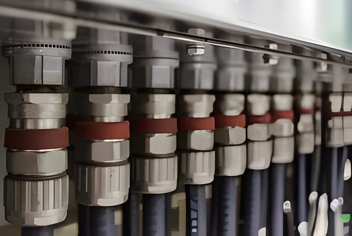
Understanding Hazardous Area Cable Gland Types
Flameproof Glands (Ex d)
Engineered to contain internal explosions, Ex d glands prevent flame transmission to the external atmosphere. Their robust construction features:
Reinforced bodies with flame paths that cool escaping gases below ignition temperatures
Mandatory barrier sealing for cables lacking extruded bedding or compact circularity (e.g., unfilled multi-core cables)
Strict certification requirements (IEC 60079-1) prohibiting interchangeability with non-Ex d glands on flameproof equipment
Critical Application Note: Post-2024 IEC 60079-14 updates eliminated the 3-meter exemption—barrier glands are now compulsory for all Zone 1 Ex d installations regardless of cable length .
Increased Safety Glands (Ex e)
Designed to eliminate sparking and overheating through enhanced mechanical security:
Anti-tamper features prevent loosening under vibration (common in compressor stations)
IP66/IP68 sealing ensures dust/water ingress cannot cause short circuits
Thermal derating requirements for high ambient temperatures (>40°C)
Restricted Breathing Glands (Ex nR)
For Zone 2 applications where hazardous atmospheres are abnormal and short-lived:
Labyrinthine seals minimize gas ingress over time
Compatible with Ex d and Ex e equipment but require validation for cable length >3 meters
Gland Classification Reference Table:
Gland Type
Sealing Mechanism
Zone Applicability
Key Cable Compatibility
Ex d (Barrier)
Resin/epoxy compound per conductor
Zone 1
Non-circular, unfilled, hygroscopic filler cables
Ex e
Elastomeric outer sheath seal
Zone 1/2
Circular, extruded bedding cables
Ex nR
Restricted breathing labyrinth
Zone 2 only
Compact cables >3m length
Material Compatibility: Beyond Corrosion Resistance
Metallurgical Considerations
Nickel-plated brass (10-12µm): Standard for most onshore applications; avoids spark risks. Ensure plating thickness exceeds IEC minimums (8µm) for H₂S resistance
316L stainless steel: Mandatory for offshore/sour environments. Beware galvanic corrosion when mating with carbon steel enclosures—use dielectric washers
Aluminum hazards: Never pair brass glands with aluminum enclosures. Electrolytic reaction causes rapid degradation. Opt for anodized aluminum glands instead
Non-Metallic Innovations
Polycarbonate Ex e glands (e.g., blueglobe PC HT): Ideal for chemical exposure zones with -20°C to +60°C range
Silicone-sealed variants: Maintain elasticity from -60°C to +160°C for Arctic or furnace applications
Material Selection Checklist: ☐ Verify enclosure material (avoid Al/brass couples) ☐ Confirm operating temperature matches gland ratings ☐ Validate plating thickness >10µm for corrosive services ☐ Require IECEx/ATEX documentation for material traceability
Step-by-Step Installation Protocol
Preparation Phase
Cable Verification: Confirm circularity with calipers. Reject cables with >5% ovality
Sheath Stripping: Strip outer sheath per manufacturer’s length specification (typically 50mm). Critical error: Damaging armor or inner bedding
Armor Treatment: Trim SWA/AWA to exact length. Use armor former tools to achieve smooth conical shape
Assembly Sequence
Component Ordering: Thread components onto cable before termination. Missing the compression nut sequence is irreparable without cutting the cable
Armor Clamping: For SWA cables, position armor wires uniformly under the cone. Overtightening deforms wires, reducing pullout strength by up to 70%
Seat Inner Seal: For Ex e glands, lubricate elastomeric seals with silicone (never petroleum gel). Verify seal contacts inner bedding—not filler material
Torque Criticality
Gland Size (mm)
Recommended Torque (Nm)
Overtightening Effect
M20
25-30
Seal extrusion, loss of IP rating
M25
30-35
Sheath cracking, gas migration path
M32
35-40
Aluminum armor shearing
M40
40-45
Enclosure thread stripping
Always use calibrated torque wrenches—never adjust by “feel”
5 Catastrophic Errors and Their Remedies
1. Certification Mismatch
Error: Installing an Ex e gland on Ex d equipment, invalidating the flameproof rating
Solution: Match gland certification exactly to equipment protection type (Ex d gland for Ex d enclosure)
2. Barrier Gland Omission
Error: Assuming standard Ex d glands suffice for unfilled cables in Zone 1
Solution: Implement barrier glands for all Ex d entries unless using certified compact cables with extruded bedding
3. Ingress Protection Complacency
Error: Using generic washers instead of manufacturer-supplied IP sealing washers
Solution: Require glands with integrated OSTG (Overtightening Stop Technology) to prevent seal deformation
4. Cross-Zoning Misapplication
Error: Deploying Zone 2 (Ex nR) glands in Zone 1
Solution: Color-code installations by zone: light blue for intrinsically safe circuits, red tags for Zone 1 glands
5. Ignoring Dynamic Stresses
Error: Direct bending of cables <2.5cm from gland, causing terminal fractures
Solution: Maintain minimum 8x cable diameter bend radius and secure with cleats within 15cm of gland
Maintenance and Inspection Regimen
Quarterly Checks:
Torque verification (re-tighten to 80% initial value if >10% loss)
Seal integrity tests using dielectric grease to detect cracking
Continuity testing for armored cables (resistance <0.05Ω)
Post-Intervention Audits: After any enclosure opening, conduct gas group re-verification—substituting glands rated for IIC (hydrogen) when original was IIB (ethylene) breaches Ex containment
The Future-Proof Installation
With IEC 60079-14:2024 raising the bar, oil and gas operators must:
Digitize gland records with IoT-enabled glands transmitting seal integrity data
Adopt lifecycle tracking via QR-coded certifications on every gland
Train installers on VR simulations of gas migration through faulty seals
“A cable gland is only as explosion-proof as its weakest seal. In hazardous areas, there is no room for approximation—only precision.” (IECEx Assessor Report, 2025)
By mastering gland selection criteria and installation rigor, oil and gas facilities transform cable entry points from vulnerability zones to fortified barriers against catastrophe. The marginal cost of premium-certified glands pales against the existential risk of compromise—a truth etched in every incident report from Piper Alpha to Deepwater Horizon.
Oil and Gas
Have Any Question?
If you have any questions, please contact us by sending an email to