SIL Verification Demystified: Applying ISA-TR84.00.02 for Safety Instrumented Functions in Oil & Gas
Introduction: The Non-Negotiable Importance of SIL Verification The catastrophic legacy of Bhopal, Flixborough, and Texas City refinery explosions underscores a brutal truth: functional safety failures in the oil and gas industry carry human, environmental, and financial costs too grave to ignore. At the heart of preventing such disasters lies Safety Instrumented Systems (SIS), whose performance hinges on rigorous Safety Integrity Level (SIL) verification. This complex but critical process ensures that Safety Instrumented Functions (SIFs) will operate with the required reliability when process conditions veer toward catastrophe. For engineers grappling with standards like IEC 61511 and ISA-84, ISA-TR84.00.02 emerges as an indispensable guide for navigating SIL verification’s quantitative and qualitative demands. This article demystifies SIL verification by translating ISA-TR84.00.02’s methodology into actionable steps, addresses pervasive industry pitfalls, and empowers you to build safer, standards-compliant facilities 39.
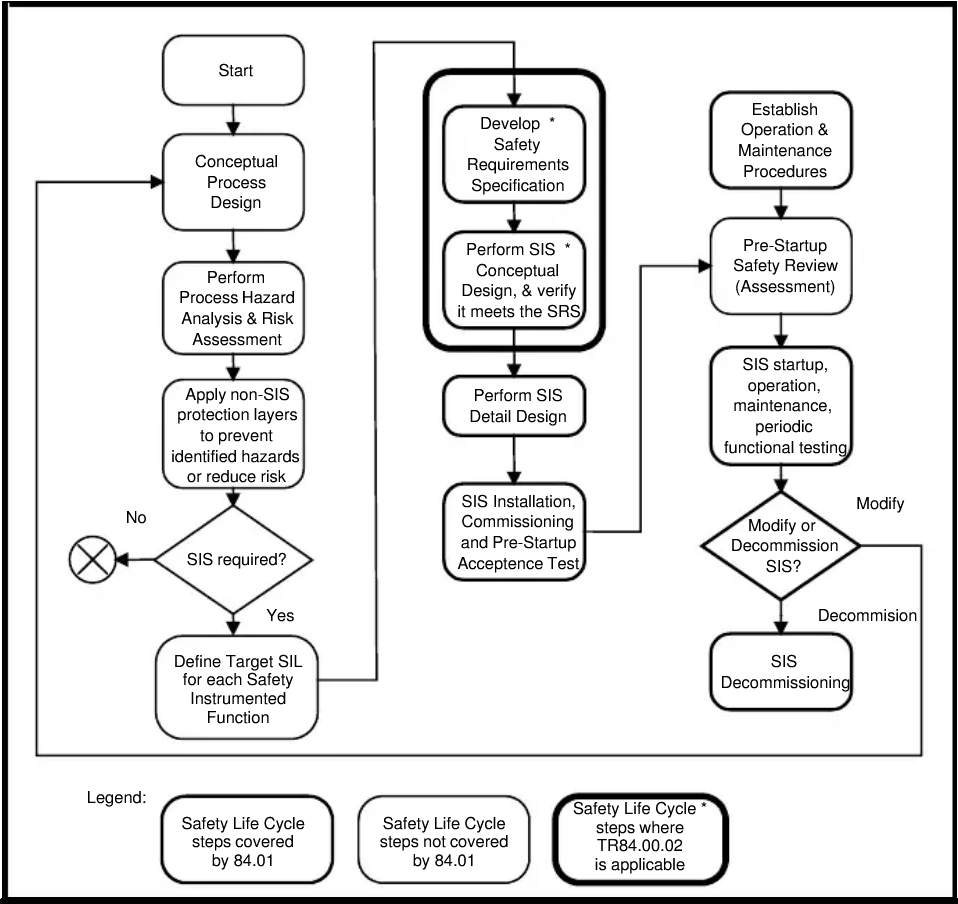
1. Understanding SIL Verification: Context within the Safety Lifecycle
SIL verification is not a standalone activity but a pivotal step within the functional safety lifecycle mandated by IEC 61511 and ANSI/ISA-84.00.01. It occurs after SIL determination (e.g., via LOPA) and before final system validation and operation.
Core Objectives:
Quantitative Validation: Prove via reliability modeling that each SIF achieves its target Average Probability of Failure on Demand (PFDavg) or Probability of Dangerous Failure per Hour (PFH).
Architectural Compliance: Ensure subsystem configurations (sensors, logic solvers, final elements) meet hardware fault tolerance (HFT) and systematic capability requirements.
Spurious Trip Analysis: Minimize production losses by quantifying Mean Time to Fail Spurious (MTTFS) 411.
For existing facilities, ISA-TR84.00.02 acknowledges the “grandfather clause” (ANSI/ISA-84.00.01), but stresses that verification remains essential for proving ongoing compliance and managing modification impacts 3.
2. ISA-TR84.00.02: Purpose, Scope, and Limitations in Oil & Gas Applications
Developed by the ISA84 committee, this technical report (TR) provides methodologies to implement IEC 61511’s quantitative verification requirements. Unlike the standard itself, ISA-TR84.00.02 is informative, not normative—yet it’s widely regarded as industry best practice.
Key Areas Covered:
Failure Data Handling: Classifying device failure modes (safe/detected, safe/undetected, dangerous/detected, dangerous/undetected) and sources for failure rates (λ).
Modeling Techniques: Formulas for PFDavg, PFH, and MTTFS calculations across diverse architectures (1oo1, 1oo2, 2oo3, etc.).
Common Cause Failure (CCF): Applying beta factors (β) and methodologies to estimate CCF vulnerability.
Diagnostic Coverage: Quantifying how diagnostics reduce undetected dangerous failures 4.
Critical Gaps to Note:
Proof Test Effectiveness: Guidance deferred until the next revision (refer to ISO 12489 meanwhile).
Continuous/High-Demand Systems: Limited modeling advice—critical for pipeline SCADA or compressor control SIFs.
Systematic Failures: Lifecycle-wide management of systematic errors (e.g., software bugs) is out of scope 4.
Oil & Gas Context: Offshore platforms, refineries, and pipelines often use partial valve stroke testing (PVST) for online verification. ISA-TR84.00.03 (mechanical integrity) supplements this TR for such applications 3.
3. Step-by-Step SIL Verification Methodology per ISA-TR84.00.02
Step 1: Define SIF Architecture & Parameters
Decompose the SIF into subsystems (sensors, logic solver, final elements).
Determined SIL: SIL 2 (PFDavg target: 0.01 – 0.001).
Original Design:
PTs: 1oo1, λ<sub>DU</sub> = 0.5/year, TI = 1 year
SDV: 1oo1, λ<sub>DU</sub> = 0.1/year, TI = 3 years
Calculated PFDavg: 0.35 (Fails SIL 2)
Redesign per ISA-TR84.00.02:
PTs: 2oo3 voting, λ<sub>DU</sub> = 0.5/year
SDV: Partial stroke tested (C<sub>PT</sub> = 80%) quarterly, full test triennially
Recalculated PFDavg: 0.008 (Meets SIL 2)
Cost Impact: Added redundancy but reduced shutdown testing downtime 39.
5. Common Pitfalls & How to Mitigate Them
Pitfall 1: Overlooking Proof Test Effectiveness
Risk: Inflated C<sub>PT</sub> values (e.g., 90% vs. actual 60%) artificially lower PFDavg. Fix: Document test procedures rigorously. Use residual risk factors (RRF) for coverage gaps 4.
Pitfall 2: Underestimating Common Cause Failures
Risk: Identical redundant devices failing simultaneously (e.g., plugged impulse lines on redundant PTs). Fix: Apply beta factors ≥5% for identical sensors/valves. Use diversity (e.g., pressure + flow for overfill protection) 11.
Pitfall 3: Ignoring Human Factors
Risk: Manual valves left in bypass post-maintenance. Fix: Include bypass probability in PFDavg models and enforce procedural controls 9.
Pitfall 4: Misapplying High-Demand Formulas
Risk: Using PFDavg for compressor anti-surge controls (high-demand mode). Fix: Use PFH (Probability of Failure per Hour) calculations for >1 demand/year 4.
6. Tools and Best Practices for Efficient SIL Verification
Software Solutions: Tools like SILcet automate PFDavg/PFH calculations using ISA-TR84.00.02 methods and integrate:
Failure rate databases (e.g., exida)
Beta factor calculators
Report generation for audits 11
Best Practices:
Leverage Plant Data: Replace generic failure rates with site-specific maintenance records.
Integrate with Mechanical Integrity: Align proof tests with preventive maintenance schedules.
Re-verify After Changes: Modifications (e.g., valve trim) impact failure rates and test coverage.
Conclusion: SIL Verification as a Safety Imperative, Not a Paper Exercise
SIL verification transcends compliance paperwork—it’s the engineering bedrock of trustworthy safety systems. In the high-hazard landscape of oil and gas, ISA-TR84.00.02 provides the methodological clarity needed to navigate PFDavg calculations, architectural constraints, and operational realities. Yet, its true value emerges only when paired with site-specific data, uncompromising testing, and cross-functional collaboration between process safety, instrumentation, and maintenance teams. By demystifying SIL verification and confronting its pitfalls head-on, engineers can transform abstract standards into tangible barriers against catastrophe—ensuring that when the unthinkable happens, the SIF responds 3911.
Takeaway: Start your next SIL verification with three questions:
“Is my failure data relevant to this specific service?”
“Could my proof tests miss critical failure modes?”
“What’s the cost of a spurious trip—and is my MTTFS acceptable?”
References & Further Reading:
ANSI/ISA-84.00.01 (IEC 61511 Mod)
ISA-TR84.00.02: Safety Integrity Level (SIL) Verification of Safety Instrumented Functions
ISO 12489: Petroleum, petrochemical, and natural gas industries – Reliability modeling
Oil and Gas
Have Any Question?
If you have any questions, please contact us by sending an email to