Geohazard Screening and Wellbore Integrity for Drilling in Seismically Active Onshore Basins
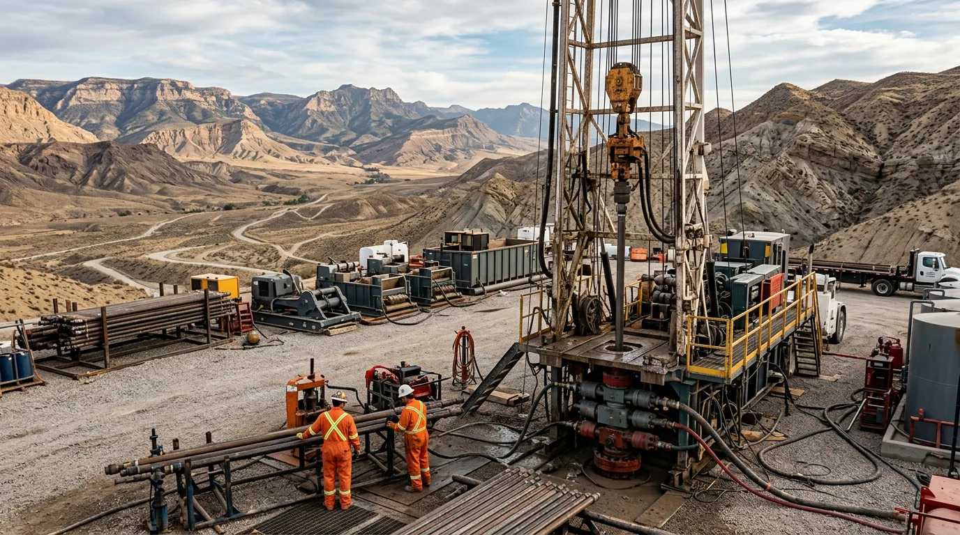
Drilling in seismically active onshore basins carries a category of risk that standard well-planning workflows don't catch. Fault reactivation, induced seismicity, shallow gas migration along fracture pathways, formation instability — any one of those can cost you the wellbore, put gas at surface, or fail the structural casing. All of it lands as non-productive time (NPT), abandonment cost, and people in harm's way. So when an operator picks up newly offered acreage in a tectonically active region, the geohazard screening starts before anyone stakes a location. Not after the drilling programme is written.
Standards and Regulatory Context
Several industry frameworks govern this work. API RP 96 sets out well barrier philosophy across the well lifecycle. For casing design where the formation may move, API 5C3 provides the basis for load case development. Seismic hazard classification for surface facilities and wellheads usually comes through local building codes aligned with ISO 19901-1, which covers seismic design for fixed offshore structures, or through onshore equivalents such as national building codes and API standards for onshore facilities. And if you're working where induced seismicity is regulated — parts of North America, the Middle East, Central Asia — check whether the national competent authority imposes traffic-light protocols on drilling and injection operations.
Phase 1: Fault Mapping and Seismic Hazard Characterisation
Regional Tectonic Review
First deliverable: a regional fault inventory. Build it from whatever you have — 2D and 3D seismic reflection data, published geological maps, satellite-based interferometric SAR (InSAR) where available, historical seismicity catalogues. The point is to separate active fault systems, the ones with documented Quaternary displacement, from inactive structural features that carry lower reactivation risk.
Where 3D coverage is thin, offset well data has to work harder. The quadrature volume — a 90° phase rotation applied to the reflectivity seismic — holds onto the high-frequency content you need for shallow hazard detection. That's how the team picked up shallow gas accumulations sitting on faults that ran upward from deeper gas-bearing reservoirs, and moved the proposed well locations off those signatures.
Fault Proximity Criteria
Once the fault inventory is built, the planning team must define exclusion zones and elevated-scrutiny zones around active faults. There are no universal numbers here. The zones depend on fault type (strike-slip, normal, reverse), estimated slip rate, and how deep the planned wellbore sits relative to the fault plane. For seismically active regions, put these questions to the geomechanical consultant:
- Is the fault critically stressed under the current stress regime?
- Could it show fault-valve behaviour, where seismic events mobilise trapped fluid and create rapid pore-pressure transients?
- Where does the planned deviated wellbore trajectory actually intersect the mapped fault planes?
Crossing an active fault with a wellbore is not automatically a programme-stopper. But it does demand specific casing design provisions and contingency planning.
Phase 2: Shallow Geohazard Assessment
Shallow geohazards in seismically active basins include, but are not limited to: shallow gas and gas hydrates, overpressured shales, active faults cutting the tophole section, and soil liquefaction potential at the wellsite. The OSIG Guidance Notes (2017) give a structured framework for shallow geohazard assessment — high-resolution seismic, geotechnical sampling, and integrated risk management through the well lifecycle.
Key attributes to map in the shallow section include:
| Hazard Type | Primary Detection Method | Offset Well Indicator |
|---|---|---|
| Shallow gas | Amplitude anomalies, bright spots | Gas cut mud returns, flow on connections |
| Overpressured shale | Velocity inversion on seismic | Tight hole, pack-off, elevated ECD |
| Active fault intersection | Fault plane mapping, seismic discontinuity | Mud losses, wellbore deviation |
| Soil instability / liquefaction | Geotechnical borehole, CPT | Surface subsidence records |
The Gale Field work shows how fault geometry at depth drives shallow hazard risk: faults bounding deeper gas reservoirs acted as migration conduits, charging shallow intervals that would otherwise look low-risk. That vertical connectivity gets underestimated all the time on newly offered acreage where deep well control is sparse.
Phase 3: Wellbore Integrity Design for Seismic Environments
Casing Architecture
Standard casing design assumes static formation loads. That isn't good enough here. In seismically active basins the design has to account for dynamic loading from fault slip, and for formation movement imposing bending loads on the string where it crosses a fault plane. Design provisions should include:
- Increased wall thickness across anticipated fault crossing intervals, picked from a site-specific geomechanical load case rather than a generic safety factor
- Connection selection that provides both tensile and compressive capacity, since fault displacement can load the casing in either direction depending on fault kinematics
- Cement design that achieves full zonal isolation across fault-intersected intervals; channelled cement in a fault zone creates a migration pathway and removes the hydraulic barrier function of the casing annulus
That work was offshore, but the methodology transfers straight across to onshore seismically active settings.
Wellbore Barrier Philosophy
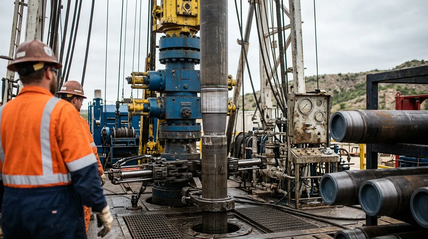
A well drilled in a seismically active basin should maintain at least two independent, tested wellbore barriers at all times during drilling operations, consistent with API RP 96 principles. In practice this means:
- The primary barrier (drilling fluid hydrostatic column) must be designed with a pore pressure profile that accounts for fault-valve pressure transients, not just the static gradient
- The secondary barrier (BOP stack and casing/cement) must be pressure-tested before entering any interval identified as elevated risk in the SSHA
- Casing shoe integrity tests should be conducted with reference to the geomechanical model, and any test result that deviates from the predicted fracture gradient at that depth should trigger a formal review before proceeding
Monitoring During Drilling
Seismically active basins warrant real-time monitoring provisions beyond standard drilling parameters. These include:
- Continuous pore pressure monitoring using MWD/LWD resistivity and sonic data, with the interpreter briefed on the specific fault-related pressure anomalies identified in the pre-drill SSHA
- Mud logging gas baseline tracking, with any sustained upward trend in background gas investigated against the pre-drill hazard map before drilling ahead
- Wellsite seismograph or microseismic monitoring where the regulatory environment or operator risk tolerance requires confirmation that drilling operations are not inducing seismicity above defined traffic-light thresholds
Illustrative Scenario
The following is illustrative and does not represent a specific named project.
An operator acquires acreage in a fold-and-thrust belt basin with documented historical seismicity. Pre-drill SSHA identifies a mapped reverse fault dipping toward the planned well location, with seismic attributes suggesting a gas-charged sand at an intermediate depth immediately above the fault hanging wall. The geomechanical model indicates the fault is critically stressed under the current compressional stress regime.
The planning team responds by: relocating the surface location laterally to reduce the fault crossing angle in the intermediate hole section; designing an additional intermediate casing string to isolate the gas-charged sand before drilling into the fault zone; specifying a cement programme with centralisation modelling to ensure full annular coverage at the fault intersection; and establishing a microseismic monitoring protocol with pre-agreed response actions if event magnitude exceeds the defined threshold.
Identify, characterise, redesign, monitor. That sequence is the operational logic the Pre-Caspian Basin SSHA study identifies as the mechanism by which structured hazard assessment reduces both NPT and geological risk.
Pre-Drill Geohazard Screening Checklist
Before a well programme is finalised on seismically active onshore acreage, confirm the following:
- Regional fault inventory completed using all available seismic, geological, and satellite data
- Active faults identified and exclusion/scrutiny zones defined with geomechanical input
- Shallow geohazard assessment conducted using quadrature or equivalent seismic attributes alongside offset well drilling incident data
- Fault-to-reservoir connectivity assessed for vertical gas migration risk in the tophole section
- Casing architecture reviewed against geomechanical load cases that include fault displacement scenarios
- Cement programme reviewed for full zonal isolation across all fault-intersected intervals
- Pore pressure profile incorporates fault-valve transient risk, not static gradient only
- Wellbore barrier test schedule defined, with decision gates before entering elevated-risk intervals
- Real-time monitoring plan specifies response actions for gas anomalies, pressure deviations, and seismic events
- Regulatory requirements for induced seismicity monitoring and traffic-light protocols confirmed
Conclusion
Geohazard screening for seismically active onshore basins is not a desktop exercise that ends when the well location is approved. It is a structured, data-driven workflow that runs from regional fault mapping through tophole shallow hazard analysis, into casing and cement design, and continues as an active monitoring programme during drilling operations.
The most effective programmes integrate all available data — seismic attributes, offset well incident records, geotechnical sampling, and geomechanical modelling — before the drilling programme is written. Do that rigorously and the well design reflects the actual subsurface risk instead of a generic template. The drilling team arrives on location with a hazard map they can use in real time.
For operators entering newly offered acreage, the immediate next step is to commission a formal SSHA that covers the full wellbore, not just the tophole section, and to ensure the output feeds directly into casing design, cement specification, and the real-time monitoring plan. Deferring that work to the post-spud phase is where NPT and integrity failures originate.