VFD Selection and Harmonic Mitigation for ESP Artificial Lift Systems
Electric submersible pump failures are among the most expensive events in artificial lift operations. When a string pulls early—whether from insulation breakdown, bearing wear, or motor winding failure—the combined cost of workover, lost production, and equipment replacement is substantial. A significant portion of premature ESP failures trace directly to power quality problems originating at the variable frequency drive. Getting VFD selection and harmonic mitigation right is not an equipment purchasing exercise; it is a reliability engineering decision that determines run life.
The Power Quality Problem in ESP Systems
A VFD converts fixed-frequency AC supply to a variable-frequency, variable-voltage output using a rectifier stage followed by a DC link and an inverter stage. The rectifier draws non-sinusoidal current from the supply, injecting harmonic currents back into the power system. The inverter produces a pulse-width-modulated output voltage that, while controllable in fundamental frequency, contains high-frequency voltage switching transients.
For a standard ESP installation, both sides of this harmonic picture matter. On the supply side, harmonic currents distort the supply voltage, affecting other loads on the same bus and potentially violating utility interconnection agreements. On the output side, the PWM voltage waveform subjects the step-up transformer, the long downhole cable, and the submersible motor to stresses that standard motor insulation was not designed to handle continuously.
Research published in Energies (Lingom et al., 2023) confirms that VFDs feeding ESP systems generate power quality disturbances that affect both the supply network and the downhole equipment, and that the failure modes differ between normal operating conditions and fault conditions. The same body of work establishes that modeling the complete system—drive, cable, transformer, and motor—is necessary to predict actual voltage stress at the motor terminals rather than relying on drive output specifications alone.
Standards and Requirements Context
Engineers specifying VFDs for ESP service should work within several overlapping frameworks:
- IEEE 519 sets limits on harmonic current injection at the point of common coupling with the utility. Compliance is typically a contractual requirement in facility interconnection agreements.
- IEC 61000-3-12 addresses harmonic current limits for equipment connected to medium- and low-voltage public supply systems, relevant where ESP installations draw from shared infrastructure.
- API 11S covers the electric submersible pump system and provides guidance on electrical system design including cable sizing and insulation requirements.
- NEMA MG1 Part 31 defines inverter-duty motor requirements, including voltage rise time and peak voltage withstand capability—criteria that directly govern whether a given filter topology is adequate.
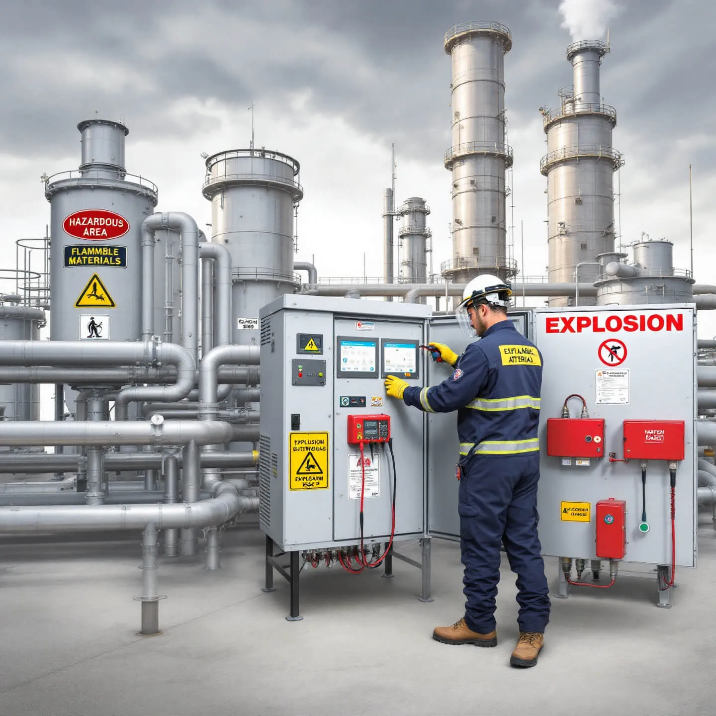
Where hazardous area classification applies, drive enclosures and associated electrical equipment must meet the relevant requirements under IEC 60079 series or the applicable national equivalent. This is non-negotiable in wellsite environments where flammable gas may be present.
Drive Sizing for ESP Service
Fundamental Sizing Criteria
ESP motors are typically three-phase induction machines operating at voltages stepped up by a surface transformer. The VFD must be sized to deliver the required torque across the full operating speed range, including startup, where current demand can be substantially higher than running current.
Key sizing inputs include:
- Motor nameplate kVA and power factor — ESP motors often have lower power factor than standard surface motors due to their elongated geometry. The VFD must supply reactive current as well as active current; size on kVA, not kW alone.
- Cable impedance — Downhole cables can extend to considerable depths. Cable resistance and inductance are not negligible; they affect voltage regulation and the resonant behavior of the output circuit. The drive output current rating must account for cable charging current.
- Derating for ambient and altitude — Wellsite enclosures in hot climates or at elevation require derating of drive output current. Obtain derating curves from the manufacturer and apply them before finalizing the frame size.
- Harmonic loading on the supply transformer — If multiple ESP drives share a common bus, the transformer supplying them must be rated for the combined harmonic loading. Underestimating this leads to transformer overheating and reduced transformer life.
Speed Range and Torque Characteristics
Centrifugal pumps follow affinity laws: flow scales with speed, head scales with speed squared, and power scales with speed cubed. This means that even modest speed reductions yield significant reductions in hydraulic power demand—a feature that makes VFD control attractive for inflow management. However, operating below the minimum recommended speed for extended periods can reduce motor cooling (which is provided by the produced fluid flowing past the motor) and must be evaluated against the manufacturer's thermal limits.
Harmonic Mitigation Options
Supply-Side Harmonics
The standard six-pulse rectifier topology generates characteristic harmonic orders at the fifth, seventh, eleventh, thirteenth, and higher multiples of fundamental frequency. Mitigation approaches include:
| Approach | Mechanism | Trade-offs |
|---|---|---|
| Line reactor (AC choke) | Adds impedance to limit harmonic current magnitude | Low cost, modest attenuation, voltage drop penalty |
| DC link choke | Smooths DC bus current | Similar attenuation to AC choke, internal to drive |
| 12-pulse drive | Phase-shifting transformer cancels fifth and seventh harmonics | Higher cost, requires dedicated transformer, eliminates dominant harmonics |
| 18-pulse drive | Three-winding phase-shifting transformer cancels lower orders further | Higher cost and complexity, effective for large installations |
| Active front end (AFE) | PWM rectifier draws near-sinusoidal current | Highest cost, near-unity power factor, regenerative capability |
| Passive harmonic filter | Tuned LC circuits provide low-impedance path for target harmonic orders | Effective but can cause resonance if system impedance changes |
| Active harmonic filter | Injects canceling harmonic currents | Flexible, handles varying harmonic spectrum, higher cost |
Output-Side Power Quality and Motor Protection
The output-side problem is distinct from supply-side harmonics and is often underweighted in procurement specifications. PWM switching produces voltage pulses with fast rise times. When these pulses travel along a long downhole cable, wave reflection at impedance discontinuities—particularly at the motor terminals—can produce peak voltages significantly higher than the DC bus voltage. This overvoltage stress degrades motor winding insulation progressively.
- Output reactor (load-side choke): Reduces voltage rise rate (dV/dt) and attenuates reflected wave peaks. Lowest cost output-side mitigation. Effective for moderate cable lengths.
- dV/dt filter: More aggressive attenuation of voltage rise rate than a simple reactor. Suitable for longer cable runs.
- Sine-wave filter: Reconstructs a near-sinusoidal voltage waveform at the drive output before the signal enters the cable. Eliminates PWM-related stress entirely.
The trade-off with sine-wave filters is cost, physical size, and the need to operate the drive at a fixed or constrained switching frequency. For critical ESP strings in high-cost wells, the runtime improvement justifies the capital premium.
Cable Considerations
Downhole cable is a critical system element that is frequently underspecified. Key considerations:
- Voltage rating: The cable must withstand both the operating fundamental voltage and the peak transient voltages produced by PWM switching. Specify cable voltage rating based on the worst-case peak voltage at the motor terminals, not the drive output voltage alone.
- Temperature rating: Cable insulation must be compatible with wellbore temperature throughout its length, including at depth where temperatures are highest.
- Impedance matching: The cable's characteristic impedance, combined with the motor's input impedance, determines the magnitude of reflected wave overvoltage. A sine-wave filter eliminates this concern; without one, the cable-motor impedance relationship must be evaluated.
- Capacitive charging current: Long cables have significant shunt capacitance. At higher operating frequencies, capacitive charging current adds to the drive output current demand. This must be included in drive sizing calculations.
Illustrative Scenario
The following is illustrative and not drawn from a specific field case in the cited sources.
Consider an onshore ESP installation with a motor rated at a voltage requiring step-up from a surface transformer, driving a pump on a cable of significant length. The installation uses a standard six-pulse VFD with no output filtering. Within the first year of operation, the operator observes repeated motor insulation failures and measurable harmonic distortion on the facility bus affecting other instrumentation loads.
A power quality assessment following the methodology described by Lingom et al. (2023) would model the complete system to identify resonant frequencies in the cable-motor circuit and quantify peak voltage at the motor terminals. The supply-side harmonic spectrum would be measured at the point of common coupling and compared against IEEE 519 limits. Based on findings, the engineer would evaluate whether a 12-pulse transformer with an output sine-wave filter justifies its capital cost against the workover and lost-production exposure from continued early motor failures—a calculation that almost always favors the filter investment for wells with significant depth and intervention cost.
Selection and Specification Checklist
Before issuing a VFD specification for an ESP application, verify the following:
- Drive sized on motor kVA (not kW), with cable charging current added to output current demand
- Ambient derating and altitude derating applied to arrive at final frame size
- Minimum and maximum operating speed range defined and confirmed against motor cooling requirements
- Supply-side harmonic study completed; mitigation topology selected to meet IEEE 519 at the point of common coupling
- Output-side mitigation selected based on cable length, cable impedance, and motor insulation voltage rating—not defaulted to "output reactor only"
- Sine-wave filter evaluated for critical or high-cost wells where run-life improvement justifies capital premium
- Cable voltage rating verified against worst-case peak terminal voltage, including PWM transients if no sine-wave filter is installed
- Drive enclosure rated for hazardous area classification at the wellsite
- Harmonic filter resonance risk assessed if passive filters are used on a bus shared with power factor correction capacitors or other loads
- System-level model (drive + transformer + cable + motor) reviewed before finalizing filter specification
Conclusion
VFD selection for ESP artificial lift is a system engineering problem, not a component selection task. The drive, the step-up transformer, the downhole cable, and the submersible motor interact in ways that determine actual voltage stress and harmonic injection—neither of which can be read from a drive datasheet in isolation.
The immediate next steps for any engineer specifying or reviewing an ESP electrical system are: conduct a system-level power quality model before finalizing the filter specification; measure supply-side harmonics at the point of common coupling on existing installations to establish a baseline against IEEE 519; and evaluate sine-wave filter economics against the specific workover cost exposure for each well. For high-value or deep wells, the runtime improvement documented in field studies makes the sine-wave filter the defensible choice. For lower-cost wells, a rigorous dV/dt analysis will determine whether an output reactor is genuinely adequate or whether a more capable filter is warranted.
Harmonic mitigation specified at the design stage costs a fraction of what it costs as a retrofit—and a fraction of what a single premature workover costs.