Diluent Blending for Extra-Heavy Crude Transport: Viscosity Targets and Diluent Recovery
Extra-heavy crude sitting in a gathering system at reservoir temperature is, for practical purposes, a semi-solid. It won't flow on its own, and pushing it through a pipeline at commercial throughput rates stalls the pumps, busts the maximum allowable operating pressure, or does both. The cost lands in a few predictable places: stranded production, damaged rotating equipment, contractual penalties at the export terminal. Diluent blending is the most widely deployed answer, and it drags its own operational and economic load with it — mainly the cost of hauling diluent to the field and getting it back out at the destination. Three engineering decisions settle whether the operation works: getting the viscosity target right, calculating the blending ratio correctly, and designing a recovery circuit that doesn't leak money.
The Viscosity Problem in Extra-Heavy Crudes
A hydrocarbon fluid used to dilute heavy oil and reduce its viscosity for easier transportation is formally defined as a diluent — typically a distillation cut such as naphtha (SLB Energy Glossary). Extra-heavy crudes, broadly those below roughly 10° API, present a harder problem than high viscosity alone. Their viscosity is acutely temperature-sensitive, and the fluid is asphaltene-dominated, so it misbehaves in ways lighter crudes don't.
Pipeline operators and shippers set a maximum viscosity specification at the inlet of the receiving system. That number is the engineering anchor for every blending calculation downstream of it.
Diluent Selection
The SLB glossary identifies naphtha as the standard diluent for heavy oil dilution and transportation. In practice, three competing criteria drive the choice:
- Viscosity reduction efficiency — lighter fractions reduce viscosity more per unit volume added, but the relationship is non-linear.
- Availability and logistics — condensate or light crude may be more accessible in remote fields than refined naphtha.
- Recovery economics — a diluent that can be cleanly separated at the destination by atmospheric distillation is far cheaper to recover than one whose boiling range overlaps the crude fraction.
Distillate-based diluents (lighter fractions) generally reach the target viscosity at lower volumetric addition rates than crude-oil diluents — the study confirmed that — but the cost advantage is set by local diluent price and recovery efficiency.
Volatility cuts both ways here. It's the asset that makes distillation recovery work, and it's the hazard that governs vapour pressure management at blending stations and terminals.
Viscosity Targets and Blending-Ratio Calculation
Setting the Target
The pipeline inlet viscosity specification is set by the operator to ensure:
- Pump operating point stays within the design envelope.
- Reynolds number remains sufficient to avoid gel plug formation at minimum throughput.
- The blend remains pumpable during transient conditions such as startup after a shutdown.
No single method is universally optimal. The interaction between temperature and diluent fraction has to be characterised experimentally for the specific crude before anyone commits to a design blending ratio.
The Blending Ratio Calculation
The volumetric blending ratio comes out of a mixing-viscosity model. The one most commonly applied in pipeline engineering is the logarithmic (ASTM D341-based) blending index approach. For a two-component blend:
Step 1 — Convert viscosities to blending indices:
The ASTM blending index W is defined as:
W = log[log(ν + 0.7)]
where ν is kinematic viscosity in mm²/s (cSt).
Step 2 — Apply the linear mixing rule:
W_blend = x_D · W_D + (1 − x_D) · W_C
where x_D is the volume fraction of diluent, W_D is the blending index of the diluent, and W_C is the blending index of the crude.
Step 3 — Back-calculate x_D for the target viscosity:
x_D = (W_target − W_C) / (W_D − W_C)
Illustrative example (values chosen only to demonstrate the method; they are not from a field record):
Suppose a crude has a kinematic viscosity of 10,000 cSt at the blending temperature, and the selected naphtha diluent has a kinematic viscosity of 1 cSt at the same temperature. The pipeline specification requires a blend viscosity not exceeding 350 cSt.
- W_C = log[log(10,000 + 0.7)] = log[log(10,000.7)] = log[4.0000] = 0.6021
- W_D = log[log(1 + 0.7)] = log[log(1.7)] = log[0.2304] = −0.6375
- W_target = log[log(350 + 0.7)] = log[log(350.7)] = log[2.5449] = 0.4056
Solving for x_D:
x_D = (0.4056 − 0.6021) / (−0.6375 − 0.6021) = (−0.1965) / (−1.2396) = 0.1585
The required diluent volume fraction is therefore 0.1585, meaning approximately 15.85 vol% of the blend must be diluent to reach the 350 cSt target under these conditions.
Check that number against laboratory rheology data for the actual crude-diluent pair before it goes into a design. The ASTM logarithmic model is an approximation, and asphaltene-rich crudes drift from it, particularly at low diluent fractions where aggregation effects take over.
Diluent Recovery
Why Recovery Is Non-Negotiable
Diluent is expensive relative to the crude it travels with. Count the round trip — diluent transported to the production field, blended, shipped to the refinery, separated, and returned — and every percentage point of unrecovered diluent is a direct operating loss.
Separation Methods
At the receiving terminal or upgrader, diluent recovery is accomplished by one or more of the following:
- Atmospheric flash — the blend is heated and pressure-reduced; lighter fractions flash to vapour and are recovered overhead. Effective for naphtha-range diluents with a clean separation from the crude fraction.
- Vacuum distillation — used when the boiling range of the diluent overlaps with light ends of the crude, requiring deeper cut-point separation.
- Stabiliser column — a dedicated fractionation column that produces an overhead diluent product suitable for recycle.
The 2024 techno-economic study explicitly evaluated recovery efficiency as a component of the overall economics, confirming that diluent selection and recovery design must be optimised jointly. A diluent that hits the viscosity target at a lower blending ratio but is a nuisance to recover can cost more overall than a slightly less efficient diluent with a high recovery rate.
Diluent Return Logistics
Recovered diluent has to get back to the production field, either by dedicated pipeline or by truck/barge where pipeline infrastructure does not exist. The volume of diluent in circulation at any time — in the production pipeline, in the receiving terminal inventory, in the return leg — represents working capital that must be sized and financed. Blending ratio directly determines this inventory requirement.
Practical Checklist for Blending System Design
- Obtain laboratory viscosity-temperature curves for the crude and candidate diluents across the full operating temperature range before selecting a diluent.
- Apply the logarithmic blending model as a first estimate; validate against measured blend viscosities at the design blending ratio and at the minimum anticipated pipeline temperature.
- Confirm the target viscosity against the pipeline operator's inlet specification, not against a generic industry value.
- Size the blending skid for the maximum diluent injection rate, including a margin for temperature excursions that increase crude viscosity.
- Verify that the diluent vapour pressure is compatible with the blending station and pipeline design pressure; consult the applicable API standard for liquid petroleum pipelines.
- Design the recovery unit cut point so that diluent overhead product meets the specification for recycle injection without reprocessing.
- Establish a diluent inventory balance — track injection volumes, recovered volumes, and losses — and set a review trigger for any sustained deviation.
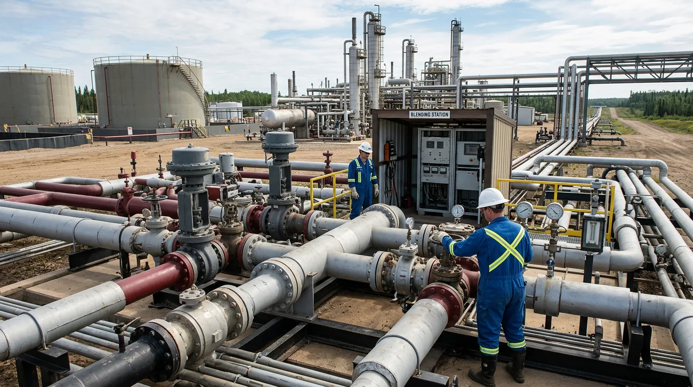
- For any blending station commissioning or diluent injection skid maintenance: apply full isolation of both crude and diluent circuits, depressurise to atmospheric, verify zero energy with calibrated pressure gauges, apply LOTO, confirm with gas detection before opening any connection, and vent safely to a closed vent header.
Conclusion
The engineering of diluent blending for extra-heavy crude transport reduces to three coupled decisions: selecting a diluent whose properties match both the viscosity target and the recovery circuit, calculating the blending ratio from a validated mixing model rather than a rule of thumb, and designing the recovery system to maximise diluent return.
The logarithmic blending index method provides a defensible starting point for ratio calculation, but it must be anchored to laboratory rheology data for the specific crude-diluent pair — particularly for asphaltene-rich streams where model deviations are well documented. The 2024 techno-economic study reinforces that diluent selection and recovery efficiency must be evaluated together; optimising only for the lowest blending ratio without accounting for recovery cost will produce a suboptimal design.
Next steps for a project team approaching this problem: commission a laboratory blending study covering at least three diluent candidates across the expected temperature range, run the techno-economic comparison including return logistics, and engage the pipeline operator early to confirm the inlet viscosity specification and any blend quality restrictions before finalising the injection system design.