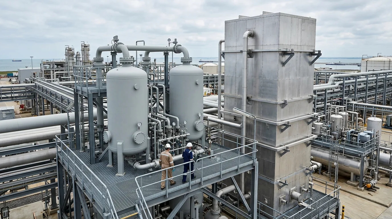
Amine unit foaming and solvent degradation are among the most operationally disruptive problems in gas sweetening. A foaming absorber can drive treated gas off-specification within minutes, forcing a plant to flare or curtail throughput. Prolonged foaming accelerates solvent losses through carryover, clogs downstream equipment, and masks the root cause while operators chase symptoms. Understanding what actually triggers foam—and how degradation feeds it—lets engineers intervene early rather than react in crisis mode.
Why Pure Amine Does Not Foam
The starting point for any troubleshooting effort is a fact confirmed across multiple laboratory and field studies: pure amine solutions do not form stable foams. Foam requires surface-active contaminants that lower interfacial tension and stabilise gas–liquid interfaces. As Pall Corporation's analysis of foaming mechanisms states, "since pure amines do not form stable foams, one or more components must be present in the treating solution in order to form a persistent foam." The practical implication is that every foaming event is a contamination or degradation event first.
Foaming Causes: A Structured Taxonomy
Liquid Hydrocarbon Carryover
Condensed hydrocarbons from the inlet gas stream are one of the most frequently identified foam triggers. Light condensate and heavier hydrocarbon fractions act as surfactants at the gas–liquid interface. Inadequate inlet separation—worn demister pads, slugging from upstream piping, or an undersized slug catcher—allows liquid carryover to bypass the absorber inlet and enter the amine directly.
Iron Sulfide and Solid Particulates
Iron sulfide (FeS) particles form continuously in sour service from corrosion of carbon steel vessels and piping. These finely divided solids accumulate at gas–liquid interfaces and mechanically stabilise foam lamellae. Removing the source—corrosion—is as important as filtering the product.
Amine Degradation Products
Thermal and oxidative degradation of the amine solvent generates heat-stable salts (HSS), degradation polymers, and surface-active by-products that are potent foam promoters.
Corrosion inhibitors, scale inhibitors, biocides, and well-treatment fluids injected upstream are highly surface-active by design. Even trace quantities reaching the absorber can cause persistent foaming; the connection is often only established after systematic source isolation.
Antifoam Overtreatment
Silicone-based antifoams are themselves surface-active. Overdosing or injecting antifoam into a system that already contains degraded solvent can paradoxically worsen foam stability by creating a heterogeneous mixture of competing surfactants.
Solvent Analysis Methods
Reliable diagnosis requires laboratory analysis of the circulating solvent. The following methods provide actionable data.
| Analysis | What It Detects | Diagnostic Value |
|---|---|---|
| Amine titration (total alkalinity) | Active amine concentration | Confirms dilution or degradation loss |
| Heat-stable salt (HSS) analysis | Acetate, formate, thiosulfate, chloride, oxalate | Quantifies degradation and contamination severity |
| Iron content (ICP-OES) | Dissolved and total iron | Indicates active corrosion and FeS loading |
| Foamability test (modified Ross-Miles or dynamic) | Foam height and stability | Direct measure of current foam risk |
| Total organic carbon (TOC) | Hydrocarbon and degradation product load | Confirms organic contamination |
| pH measurement | Solvent alkalinity balance | Flags HSS accumulation and acid contamination |
The Ayalytical FoamDDI system automates foam testing to differentiate high-foam from low-foam amine solutions reliably, removing the subjectivity of manual tests.
Sampling discipline matters as much as the analysis itself. Samples drawn from the absorber sump, the rich amine line before the flash vessel, and the lean amine return line provide a profile of where contamination enters and how it evolves through the circuit. Samples should be taken in clean, sealed containers, chilled if iron analysis is required, and analysed promptly to prevent continued oxidation.
Corrective Actions
Source Elimination First
Treating symptoms—antifoam injection, reduced gas rate—without eliminating the source produces temporary relief and progressive solvent degradation.
Upstream separation should be inspected and restored to design performance. This means verifying demister pad condition, checking slug catcher liquid levels, and confirming that any upstream chemical injection points are properly rated and controlled. Where well-treatment chemicals are suspected, coordinate with the production chemistry team to identify the specific product and confirm whether it is compatible with the amine system.
Mechanical Filtration
Solid particle removal through mechanical filtration is essential in sour service. A properly sized and maintained particulate filter on the lean amine stream removes FeS before it re-enters the absorber. A carbon (activated charcoal) filter downstream of the particulate filter adsorbs surface-active degradation products and residual hydrocarbons.
Filter elements should be changed on a condition basis driven by differential pressure trend and iron analysis, not on a fixed calendar schedule. Bypassing filters during changeout, even briefly, recontaminates the solvent.
Reclaiming and HSS Removal
When HSS concentrations are elevated, reclaiming is required. The choice of reclaiming method depends on amine type, HSS composition, and whether the unit can support a side-stream reclaimer in continuous operation.
Antifoam Management
Antifoam injection should be metered at the minimum effective dose, injected at a point where it will be well dispersed, and re-evaluated regularly.
Illustrative Scenario
The following is an illustrative scenario constructed to demonstrate the diagnostic logic; it is not drawn from a documented case in the cited sources.
A gas plant running an MDEA absorber begins showing elevated differential pressure across the absorber and increased amine carryover to the outlet separator. Operators inject antifoam; differential pressure drops temporarily but returns within hours. A solvent sample is pulled from the absorber sump and sent for analysis. Results show elevated HSS (acetate and formate dominant), high total iron, and a foamability test result in the high-foam band. Upstream, a corrosion inhibitor injection pump had been recently commissioned on the inlet gas line with no compatibility check against the amine solvent. The inhibitor formulation contained a surfactant carrier. Corrective actions: the incompatible inhibitor was replaced with an amine-compatible formulation; particulate and carbon filtration were brought back on-line after a bypass period; a side-stream reclaimer was commissioned to reduce HSS load. Foaming frequency declined progressively over subsequent weeks as solvent quality improved.
Diagnostic Checklist
Before each corrective action, work through the following in sequence:
- Before any equipment entry, sample point opening, or confined space work: confirm isolation, depressurisation, zero-energy verification, LOTO, gas detection (H₂S and oxygen), and safe venting procedures are in place. These are mandatory prerequisites, not optional steps. All work must be conducted under a formal permit-to-work system with atmospheric testing and rescue standby.
- Pull solvent samples from absorber sump, rich amine line, and lean amine return; send for full suite including HSS, iron, foamability, and TOC.
- Review upstream separation performance: demister condition, liquid level control, slug catcher inventory trend.
- Audit all chemical injection programmes upstream of the absorber for surfactant content and amine compatibility.
- Check particulate and carbon filter differential pressures; confirm filters are on-line and not bypassed.
- Review antifoam injection rate and product selection; confirm dose is at minimum effective level.
- Compare current HSS analysis against the commissioning baseline and trend over recent months.
- Identify whether foaming correlates with specific operating events: feed gas composition shifts, rate changes, startup after a maintenance outage.
- Document findings and corrective actions in the plant's foaming log to build a site-specific history.
Conclusion
Foaming in amine sweetening units is always a symptom of contamination or degradation, never a property of the amine itself. Systematic diagnosis—starting with solvent analysis, tracing contamination sources upstream, and restoring mechanical protection systems—resolves the root cause rather than suppressing the symptom. Antifoam injection buys time; it does not fix the problem. The next step for any plant experiencing recurring foaming is to implement a regular solvent analysis programme, establish baseline HSS and iron levels at commissioning or after a clean solvent charge, and use deviations from that baseline as the primary trigger for investigation. Plants that treat solvent quality as a routine monitored parameter rather than an emergency response item experience significantly fewer foaming events and lower long-term solvent replacement costs.