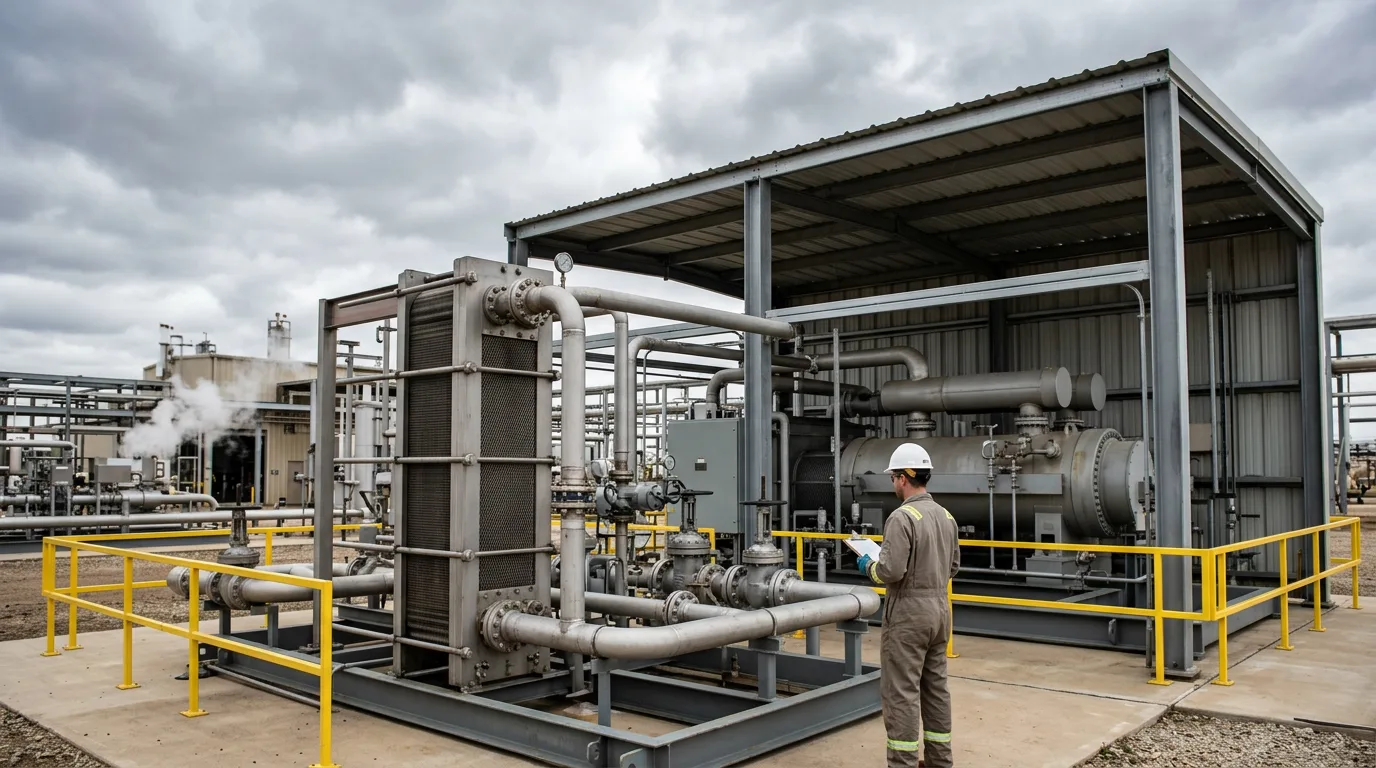
Hazardous area drawings in gas plants usually go wrong at the start. Someone classifies from the equipment footprint instead of the release. A compressor house ends up as one Zone 2 block, and a pig launcher gets a generic circle. Ask later why the boundary sits where it does and nobody can tell you. The cost shows up in two ways. An over-classified plant carries Ex-certified equipment, inspection scope and permit restrictions that buy no safety. An under-classified plant puts ignition sources where a flammable atmosphere can plausibly form, and maintenance changes quietly wear away the assumptions underneath. The source-of-release method fixes this. Every zone becomes traceable to a specific release point, its grade, and the ventilation that disperses it.
Standards and requirements context
The core reference for gas atmospheres is IEC 60079-10-1 (Explosive atmospheres – Part 10-1: Classification of areas – Explosive gas atmospheres). Edition 3.0 was published in December 2020. The method is simple to state: identify the sources of release, grade them, assess ventilation, then assign zone type and extent.
For natural gas installations in the UK and elsewhere, IGEM/SR/25 (Hazardous area classification of natural gas installations, Edition 2 with amendments, 2013) sits alongside the BS EN adoption of IEC 60079-10-1 and goes further into detail. IGEM and DNV also publish an IGEM/SR/25 calculator (2023) for release and extent calculations on natural gas.
Other standards sit downstream of the classification:
IEC 60079-14(Explosive atmospheres – Part 14: Electrical installations design, selection and erection) uses the zone, gas group and temperature class to drive equipment selection.IEC 60079-17(Explosive atmospheres – Part 17: Electrical installations inspection and maintenance) defines the inspection regime for installed Ex equipment.
The HSE's COMAH technical measures guidance treats area classification and control of ignition sources as one linked measure. A classification is only worth as much as the ignition control it drives.
Zones track how likely an explosive gas atmosphere is to be present:
- Zone 0: present continuously, for long periods or frequently.
- Zone 1: likely to occur occasionally in normal operation.
- Zone 2: not likely in normal operation, and if it occurs, only for a short time.
The source-of-release method
Step 1: Identify the sources
Walk the P&IDs, then walk the plant. List every point where flammable fluid could get into the atmosphere. Prime Process Safety describes the same sequence: material review, release source identification, ventilation assessment, then ignition risk analysis. Check for:
- Vent and flare-header discharge points
- Relief valve tailpipes that vent to atmosphere
- Compressor seal vents and packing vents
- Pig trap closures and drain connections
- Sample points and analyser vents
- Instrument and pneumatic vents where process gas is the medium
- Flanges, valve stems, threaded joints and other potential leak points
Record the fluid for each one. Its composition decides the gas group, the temperature class, and whether the vapour is lighter or heavier than air. Dense vapours from condensate or LPG-rich streams pool in pits, trenches and bunds. Lean natural gas generally rises and disperses.
Step 2: Grade each release
IEC 60079-10-1 uses three grades:
- Continuous: continuous, or expected for long periods. An example is a process vent that flows all the time.
- Primary: likely to release periodically or occasionally in normal operation. Examples are a sample point opened routinely or a pig trap opened for pigging.
- Secondary: not expected in normal operation, and if it does release, only infrequently and briefly. Examples are flange gaskets, valve glands and normally closed drains.
Grading is a judgment about normal operation, so write the reasoning into the classification record. The common error is grading a seal vent that is always flowing as secondary because "it is only a small leak." If it flows in normal operation, it is not secondary.
Step 3: Assess ventilation
Under the standard, ventilation has two parts: the degree of dilution (high, medium or low) and its availability (good, fair or poor). Dilution depends on release rate, air movement around the source and the geometry of the space. Availability asks how reliably that ventilation actually exists.
Natural ventilation in open plant is often enough for dilution, but it is never guaranteed. Closely packed modules, wind-shadow behind large vessels, solid walls and low-lying pits all weaken it. In enclosed buildings such as compressor houses the questions get narrower. Is the mechanical ventilation reliable? Is its failure alarmed? Can the release be diluted before the atmosphere reaches the flammable range?
Step 4: Assign zone type and extent
The grade sets the starting point, and ventilation moves it:
| Release grade | Zone tendency | Effect of better dilution and availability | Effect of poorer dilution or availability |
|---|---|---|---|
| Continuous | Zone 0 | Extent shrinks, and in some cases becomes negligible (Zone 0 NE) | Zone 0 extent grows and may extend into a surrounding Zone 1 |
| Primary | Zone 1 | Extent shrinks, and the surrounding area may drop to Zone 2 | Zone 1 extent grows, possibly toward Zone 0 |
| Secondary | Zone 2 | Extent shrinks, and in some cases becomes negligible (Zone 2 NE) | Extent grows, and a persistent secondary release may need a higher zone |
Extent is the distance from the source to where gas concentration has dispersed below a fraction of the lower flammable limit. It comes out of release rate, fluid properties and ventilation. It is not read off a generic radius. For natural gas, IGEM/SR/25 and its calculator exist to make this repeatable. As the US Made Supply summary of a classification package also notes, a hazardous area drawing should show plan and elevation views, the class or zone and gas group for each area, and the source of release behind each one. Elevation matters. A release can run downward into pits and upward into roof voids or ventilation intakes.
Where classifications typically go wrong
- Blanket zones. A whole building gets declared Zone 2 without anyone asking which sources justify it or whether ventilation supports it.
- Ignoring the operating mode. Sampling, pigging, filter changeout and maintenance venting are normal operations. They create primary grades even when they happen on a schedule.
- Treating relief valves as continuous hazards. A relief valve discharging to a safe location does not create a zone at the plant. One discharging to atmosphere at a low point does need assessment, but as an infrequent release, not a continuous source.
- Stale ventilation assumptions. A new enclosure, a blanked louvre or relocated equipment changes dispersion, and nobody updates the drawing.
- Using a general guideline as the calculation. Guidelines such as the EGPC-PSM-GL-014 hazardous area classification guideline describe the process. They do not replace the calculation basis in IEC 60079-10-1 or, for natural gas, IGEM/SR/25.
Illustrative example: pig launcher and adjacent compressor shelter
This scenario is constructed for illustration. It is not drawn from a real facility and uses no numerical dimensions, because extents must come from a site-specific calculation.
A gas plant has a pig launcher on open ground beside a compressor shelter that is open on two sides. The fluid is lean natural gas, which is lighter than air.
- Sources identified. The launcher closure, a drain, a vent valve used for depressurisation before opening, the vent tailpipe, valve stem and flange leak points on the trap, and the compressor seal vent and flange joints inside the shelter.
- Grades assigned.
- Closure opening and the pre-opening vent: primary, because they happen in normal operation each time the trap is used.
- Trap flanges and valve glands: secondary.
- Compressor seal vent routed to a safe location: no atmospheric release in normal operation. The seal vent connection joints are secondary.
- A vent valve discharging directly to atmosphere during depressurisation is treated as primary.
- Ventilation assessed. The launcher sits on open ground, so dilution is generally good and natural ventilation is available whenever the wind blows. The assessor should check for wind-shadow near the shelter wall. The shelter is open on two sides, but if equipment inside restricts air movement near the seals, dilution there may be only medium and availability only fair.
- Zones assigned.
- Primary releases at the launcher closure and vent give a Zone 1 volume around each source, surrounded by Zone 2 where the calculation shows a flammable atmosphere persisting beyond that volume.
- Trap flanges and valves generate small Zone 2 volumes that may merge into the Zone 1 envelope.
- Inside the shelter, the secondary releases give Zone 2, with the extent checked against the weakest-ventilated corner rather than the average.
- Record. The drawing shows each source, its grade, the ventilation reasoning, and the resulting zone, gas group and temperature class. It links the extents to the calculation.
The inspection consequence follows directly. Equipment inside the Zone 1 envelope around the launcher needs suitable protection under IEC 60079-14 selection rules, and the inspection plan under IEC 60079-17 should reflect that equipment's installed location.
Inspection and operational safety
Classification feeds the Ex inspection register, so inspectors should challenge it when site conditions don't match it. A vent now discharging somewhere new, a new enclosure, or equipment installed in an area where its protection type doesn't match the zone: each one is a reason to reopen the classification.
Any work that opens, depressurises or inspects hydrocarbon-containing equipment in these areas needs the full safe system of work:
- Isolate the equipment positively, with double block and bleed where the system design provides it.
- Depressurise through the designed route to a safe vent or flare, never to the work area.
- Verify zero energy at the equipment, including trapped pressure between valves, before breaking containment.
- Apply lockout/tagout to isolation points and energy sources.
- Observe hazardous-area precautions. Use only equipment and tools suitable for the zone, and do not open live Ex enclosures in a classified area without a permit that addresses it.
- Gas-test before and during the work, and use fixed or portable detection suited to the gas.
- Vent safely, and make sure the vented gas cannot reach ignition sources or occupied areas.
Checklist for reviewing a classification
- Every zone on the drawing traces to a named source of release.
- Each source has a stated grade, with the reasoning given for normal operation.
- Fluid properties are recorded: gas group, temperature class and lighter or heavier than air.
- Ventilation is assessed for dilution and availability, not assumed from "outdoors".
- Extents come from a calculation basis, such as IEC 60079-10-1 or IGEM/SR/25 for natural gas.
- Elevation views show pits, roofs and ventilation intakes.
- Sampling, pigging, filter changes and venting are treated as normal-operation releases.
- Management of change triggers reclassification when equipment, enclosures or vent routes change.
- The Ex equipment register matches the zones, gas groups and temperature classes on the drawing.
- Inspection grades and intervals consider the installed zone.
Conclusion
A defensible classification is a record of reasoning, not a map of circles. Start with the release, grade it honestly, test the ventilation assumptions against the real layout, and calculate extents with the method in IEC 60079-10-1, supported by IGEM/SR/25 for natural gas. For next steps, pick the largest classified area in your plant, choose three sources at random and trace each one from the drawing back to its grade, ventilation basis and calculation. Where the trail breaks, reclassify that area and update the Ex equipment register.