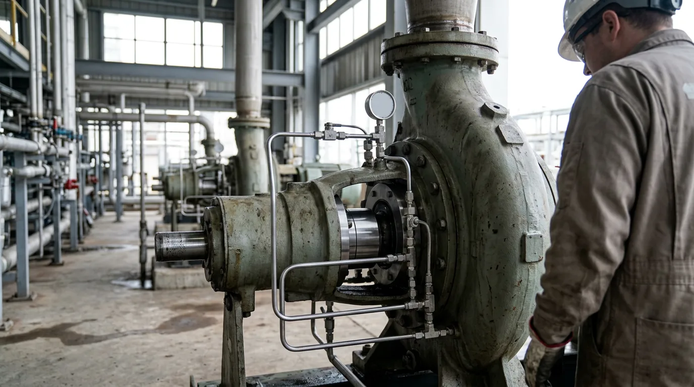
Why Sour Crude Pump Seals Keep Failing — and How to Stop the Cycle
Ask any rotating equipment engineer what keeps them up at night and sour crude pump seals will come up. One mechanical seal failure is a bad day. A repeating one is a money pit. Dissolved hydrogen sulphide (H₂S), entrained solids, high vapour pressure, and a water cut that wanders — all of it lands on the seal assembly at the same time. Miss the root cause and the replacement seal dies the same death as the one you just pulled. The pattern only breaks when someone works through fluid chemistry, seal arrangement, flush plan, and material selection together, in that order, instead of jumping straight to the parts catalogue.
That is the process this article walks through. API 682 (Pumps — Shaft Sealing Systems for Centrifugal and Rotary Pumps) is the governing framework throughout, backed by published material selection guidance for H₂S service.
Understanding the Sour Crude Environment
Sour crude is not one fluid. H₂S concentration, water cut, temperature, sand loading, and whatever amine treating chemicals are in the stream all shift from field to field — and often from one production stage to the next. Every one of those variables pushes seal component selection in a different direction.
H₂S goes after metal and elastomer by two separate routes. Sulphide stress cracking (SSC) hits high-strength steels and certain nickel alloys when tensile stress, a susceptible microstructure, and H₂S partial pressure line up at the same moment. Wet H₂S also blisters and cracks carbon and low-alloy steels through hydrogen-induced cracking. Elastomers have their own problems: standard nitrile compounds suffer rapid explosive decompression damage when pressure cycles, and conventional fluorocarbon (FKM/Viton) elastomers degrade at elevated temperatures or where amines are present.
The Flowserve product pipeline pump application guide makes the point that crude oil service demands close attention to vapour pressure, because flashing at the seal faces blisters the faces and accelerates wear. In sour crude you get a second hit on top of that — dissolved gas breaks out of solution as pressure drops across the seal chamber.
API 682 Arrangement and Category Selection
API 682 gives you three arrangements and three categories. Sour crude narrows the field fast.
Arrangement 1 (single seal) works only where H₂S concentration is low, local regulations do not classify the fluid as toxic, and a controlled leakage path to a safe collection point exists. Most sour crude services blow straight past that threshold. A single seal simply carries too much environmental and safety risk.
Arrangement 2 (dual unpressurised, tandem) pairs a primary seal with a containment seal, backed by a buffer fluid held below process pressure. The outboard seal catches whatever the primary leaks and routes it to flare or vapour recovery. Midstream crude transfer is where you see this most — H₂S present, but the operator can tolerate primary seal wear between planned maintenance intervals.
Arrangement 3 (dual pressurised, double seal) keeps a barrier fluid above process pressure. Process fluid never sees atmosphere, even while the primary seal wears. High H₂S concentrations, high vapour pressure crude, or any location where an atmospheric release is unacceptable — Arrangement 3 is the right call, because it handles vapour pressure management and H₂S containment in one move.
Category Selection
API 682 Category 1 covers general refinery service. Category 2 and Category 3 tighten the dimensional, material, and testing requirements step by step. Sour crude pumps in upstream or midstream service that fall under API 610 pump specifications should be running Category 2 or Category 3 seals. Go Category 3 when the fluid is highly toxic, when the pump is in critical service with no installed spare, or when a seal failure could mean a significant H₂S release.
Seal Plan Comparison for Sour Crude Duty
The flush plan matters as much as the arrangement. Here is how the plans that come up most often in sour crude service stack up.
| Plan | Description | Suitability for Sour Crude | Key Limitation |
|---|---|---|---|
| Plan 11 | Recirculation from pump discharge to seal chamber | Acceptable only if crude is clean, cool, and vapour pressure is well managed | Recirculates H₂S-laden fluid; no dilution benefit |
| Plan 21 | Discharge recirculation through cooler | Improves temperature margin; still recirculates process fluid | Cooler fouling with waxy or sandy crude |
| Plan 23 | Pumping ring circulates seal chamber fluid through dedicated cooler | Best thermal management for single seals in hot service | Requires clean flush; not suitable if crude flashes |
| Plan 32 | External clean flush injected into seal chamber | Dilutes H₂S at faces; controls vapour pressure | Requires compatible clean fluid source and flow control |
| Plan 52 | Buffer tank for Arrangement 2 outboard seal | Captures primary leakage; vents to flare | Tank must be monitored; rising level indicates primary seal wear |
| Plan 53A/B/C | Pressurised barrier fluid for Arrangement 3 | Prevents any process contact with atmosphere | Barrier fluid must be compatible, non-reactive with H₂S |
| Plan 54 | External pressurised barrier fluid supply | High reliability for critical double seals | Requires centralised barrier system; higher capital cost |
For most sour crude applications above a moderate H₂S partial pressure, the practical choice is Arrangement 2 with Plan 52 or Arrangement 3 with Plan 53A or Plan 54.
Material Selection for H₂S Service
Face Materials
Carbon-graphite on silicon carbide (SiC) is the standard pairing for hydrocarbon service. Sour crude with sand or abrasives changes that — go hard-on-hard (SiC versus SiC), because carbon faces erode fast once there is grit in the stream.
Tungsten carbide faces resist abrasion well, but binder selection matters, and you still need to check the specific H₂S partial pressure and temperature before signing off.
Elastomers
This is where most sour crude seal failures originate when the root cause is material-related.
Springs and Metal Components
Standard 316 SS springs are fine in mild sour service. Severe duty is a different story — Hastelloy C-276 springs take SSC out of the equation.
Illustrative Scenario: Repeated Failures on a Crude Transfer Pump
The following is an illustrative scenario, not a documented incident.
A reliability engineer is looking at a crude transfer pump with three seal failures in eighteen months. The pump handles sour crude with measurable H₂S. Installed seal: a single Arrangement 1 with Plan 11 flush, standard FKM O-rings, and carbon versus SiC faces. Pull the failed seal and the O-rings are hard and cracked — chemical degradation. The carbon face is blistered — vapour flashing at the seal faces.
The corrective path: upgrade to Arrangement 2 with Plan 52 (buffer tank vented to flare), swap FKM for AFLAS secondary seals, drop the carbon primary ring for sintered SiC to get a hard-on-hard pair, and verify the seal chamber pressure margin against the fluid vapour pressure at operating temperature. If H₂S concentration warrants it, escalate to Arrangement 3 with Plan 53A.
Pre-Selection Checklist for Sour Crude Seal Specification
Before the seal data sheet or the purchase order goes out, confirm all of the following:
- Obtain a certified fluid analysis including H₂S partial pressure, water cut, sand content, and any treating chemical composition (amines, corrosion inhibitors).
- Classify the fluid under
API 682toxicity and vapour pressure criteria to determine whether Arrangement 2 or Arrangement 3 is required. - Confirm seal category (Category 2 or 3) against pump criticality and consequence of failure.
- Select AFLAS as the default elastomer for any service with confirmed H₂S or amine presence; document the justification if an alternative is chosen.
- Specify sintered SiC versus sintered SiC face combination where sand or abrasives are present.
- Specify Hastelloy C-276 or equivalent for springs and hardware if H₂S partial pressure exceeds the threshold for 316 SS SSC susceptibility at the operating temperature.
- Confirm flush plan compatibility: Plan 52 buffer tanks must be monitored for rising level as a primary seal wear indicator; Plan 53A accumulators require periodic nitrogen top-up and pressure checks.
- Verify that the barrier or buffer fluid for Plans 52/53 is chemically compatible with both the process fluid and the seal faces.
- Require material traceability certificates and hardness testing records for all metallic components in H₂S contact, consistent with
NACE MR0175/ISO 15156limits. - Confirm that gland vent and drain connections are routed to a closed safe system, not to atmosphere.
Conclusion
Three root causes account for nearly every repeat seal failure on sour crude pumps: the wrong seal arrangement for the H₂S and vapour pressure conditions, the wrong elastomer (standard FKM where AFLAS is needed), or a flush plan that recirculates sour fluid without addressing vapour pressure margin. API 682 gives you the framework to work all three at once.
If you are staring at a repeat failure pattern, pull a current fluid analysis first, then map the results against the API 682 arrangement and category selection criteria before you specify the replacement. Change only the seal and you will reproduce the failure. The material upgrades — AFLAS elastomers, sintered SiC faces, Hastelloy C-276 hardware — cost little next to a single unplanned shutdown. Treat them as the baseline specification for confirmed sour service, not as an optional upgrade.