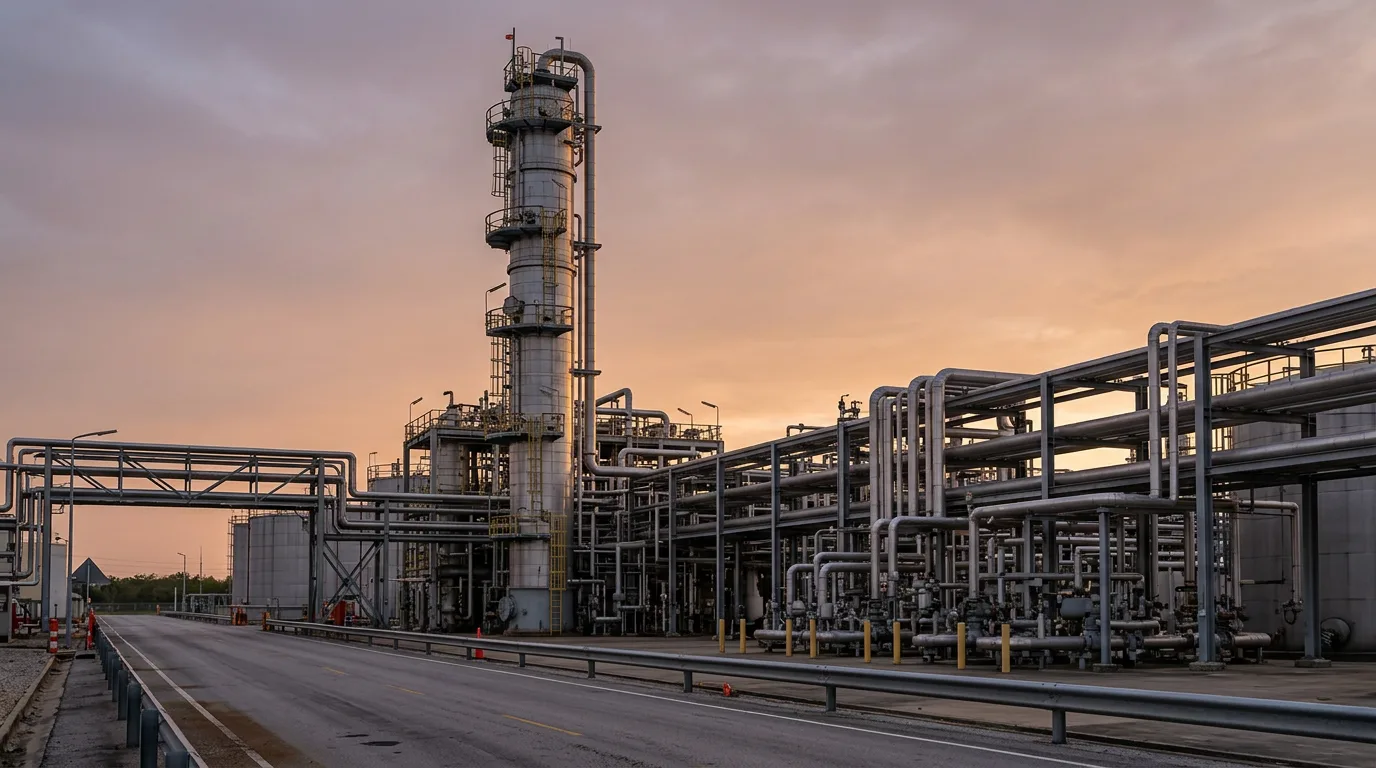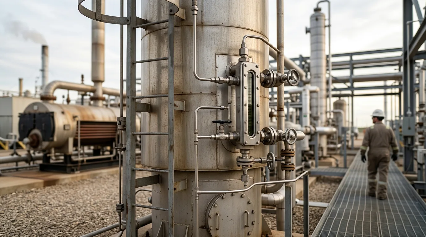
Glycol that leaves a TEG unit anywhere except as lean product costs you three times. You pay for make-up, you risk wet gas reaching the sales line, and you create an emissions and housekeeping problem. Foaming, fouled exchangers and a poorly tuned still often show up in the same unit at the same time, and the symptoms overlap enough that operators tend to chase the wrong one. Higher glycol consumption, rising reboiler fuel use, a dew-point excursion and a benzene emissions inventory that no longer matches the permit are often one set of causes seen from different angles. This guide works through them in the order you would walk the unit.
Standards and regulatory context
Two references frame most TEG troubleshooting work.
API Spec 12GDU covers design and manufacture of glycol-type gas dehydration units. Use it to confirm the installed equipment meets the original design specification. Only then can you blame operating conditions for a symptom, rather than a design limit. It sets the baseline for what the equipment was built to do.
40 CFR Part 63 Subpart HHis the US national emission standard for hazardous air pollutants from oil and natural gas production facilities. It is the main driver for BTEX control on glycol dehydrators in the US. Applicability, thresholds and compliance options depend on facility type and permit, so check them against your own authorisation. Outside the US, local air permits usually impose similar benzene or VOC reporting.
Operating guidance mainly comes from the EPA Natural Gas STAR lesson Optimize Glycol Circulation and Install Flash Tank Separators in Glycol Dehydrators, the Bryan Research & Engineering paper Influence of Process Operations on VOC and BTEX Emissions from Glycol Dehydration Units, and the KLM Technology Group natural gas dehydration design guideline.
Mapping where the glycol goes
A 2019 SPE paper on glycol loss in upstream gas dehydration (Abu Dhabi International Petroleum Exhibition and Conference, 2019) used operating data analysis to separate the loss mechanisms. That is the right approach. Before you touch any equipment, reconcile make-up volumes against the operating history and sort the loss into four buckets.
Carryover from the contactor
Liquid glycol entrained in treated gas is the classic loss path. It gets worse with foaming, a tired mist extractor, excessive gas velocity and liquid slugs from upstream. Check the outlet scrubber or downstream knockout for glycol. Watch the contactor level controller for erratic movement, and compare differential pressure across the contactor against the commissioning baseline.
Vaporisation and carry-over at the still
Glycol vapour and fine mist leave with the regenerator overhead when the still column floods, the packing is damaged or the reflux is lost. Excess stripping gas and overheated reboilers make it worse. A still that "smokes" glycol is a loss path and an emissions problem at the same time.
Leakage and mechanical losses
Pump seals, filter change-outs, drains, sample points and overflow from the surge tank are unglamorous, but they often add up. Data analysis helps here. A loss that does not correlate with throughput, gas composition or temperature points to housekeeping, not process upset.
Degradation
Degraded glycol does not vanish. It loses its water-removal capacity and forms acids and solids, which then drive foaming and fouling. Treat degradation as a root cause of foaming and fouling that feeds the other loss mechanisms. It is not really a loss path in its own right.
Diagnosing foaming
Foam cuts contact between the TEG and the wet gas, so you lose glycol and treatment performance together. In practice you see dew-point excursions and carryover at the same time.
Typical triggers
- Liquid hydrocarbons carried over from the inlet separator, especially condensate that wets the glycol.
- Production and well-treatment chemicals such as corrosion inhibitors, which act as surfactants.
- Fine solids, including iron sulfide, that stabilise foam films.
- Degraded glycol and accumulated salts.
Why a single indicator misleads
Two practical points come out of this. First, a flat ΔP does not rule out foaming. Combine ΔP, level behaviour, outlet-gas carryover and glycol appearance before you call it. Second, a carbon filter with no guard filter downstream can shed carbon fines into the circulating glycol and feed the very problem it was installed to fix.
Response sequence
- Confirm and fix the inlet separation: liquid level, internals and condensate carry-under.
- Sample lean and rich glycol, and check for hydrocarbons, solids, pH, salts and degradation products.
- Check filtration order: particulate filter, then carbon, then a guard filter after the carbon.
- Consider antifoam only as a temporary measure, and dose it sparingly. Overdosing can stabilise the foam and hide the root cause.
- Find the chemical source. If a new inhibitor or treatment chemical coincides with the onset, bring the chemical supplier in.
Reboiler chemistry and rich-lean exchanger fouling
Reboiler and glycol quality
Glycol degrades when it sees excessive reboiler temperature, local hot spots on the fire tube or oxygen. The degradation produces acidic species, so pH drift is an early warning. It is also corrosive and promotes more foaming. Keep these under control:
- Reboiler skin and bulk temperatures within the glycol supplier's limits, with attention to fire-tube heat flux and deposits that create hot spots.
- A working inert or fuel-gas blanket on the surge tank to keep oxygen out.
- Glycol pH held within the range the supplier recommends, using only the neutralising additives the supplier specifies, in the quantities they direct.
- Regular glycol analysis, with the results trended rather than read as one-off checks.
Rich-lean exchanger
Fouling here is easy to miss because the unit keeps running. You see a lower rich-glycol temperature entering the still, more reboiler fuel for the same circulation, a hotter lean glycol return to the contactor and sometimes a rising still-column temperature. Hot lean glycol entering the contactor cuts absorption capacity and raises glycol vaporisation to the sales gas. It also changes BTEX absorption (see below).
The foulants are usually degradation products, carbon fines, iron sulfide and salts. Trend exchanger approach temperatures against the commissioning data. If you see drift, clean before the contactor temperature starts limiting dehydration.
Safety when opening glycol equipment
Glycol equipment holds hydrocarbons, H₂S in some services and hot fluid. Before you open a filter, exchanger, still or surge tank:
- Isolate the item positively, using double block and bleed or blinds as per site procedure.
- Depressurise and drain to a safe, closed location. Vent vapours to flare or a safe location, not to atmosphere.
- Verify zero energy: pressure gauges at zero, drains open, and temperature verified by thermometer or thermal imaging to be below 50 °C (122 °F) or the site safe-to-touch limit.
- Apply lockout/tagout to pumps, burner and any heat source.
- Treat the area as hazardous: no ignition sources, appropriate tools and PPE, continuous or frequent gas detection including H₂S and LEL, and ventilation.
- Handle spent filter elements as hydrocarbon-contaminated waste.
BTEX and VOC emissions
Raw gas often carries benzene, toluene, ethylbenzene and xylenes. The glycol absorbs a portion of these in the contactor, and they come out again with the regenerator overhead vapour. The EPA testing programme Glycol Dehydrator BTEX and VOC Emissions Testing Results at Two Units in Texas and Louisiana (March 1995) measured emissions from real units and is still a useful reference for where the vapours end up. The BR&E paper shows how process operating choices change the result.
Operating levers
| Lever | Effect on BTEX/VOC | Trade-off |
|---|---|---|
| Glycol circulation rate | Higher circulation carries more aromatics and dissolved light hydrocarbons to the still and flash tank | Too little circulation risks failing the dew-point target |
| Contactor temperature | Colder contact generally absorbs more BTEX; hot lean glycol reduces it but raises glycol vaporisation and weakens dehydration | Dehydration performance and glycol loss limit how far this can be used |
| Contactor pressure | Higher pressure increases absorption of hydrocarbons into glycol | Set by the process, so it is not a free control |
| Lean glycol purity and stripping gas | Affects dehydration and the vapour load leaving the still | Stripping gas adds to the vent volume to be controlled |
| Flash tank | Removes dissolved hydrocarbons before the still | Needs a destination for the gas, such as fuel or a vapour recovery unit |
| Still overhead condenser | Condenses a portion of the water and heavier hydrocarbons | Non-condensables still need control |
What the Natural Gas STAR lesson recommends
Two measures are well supported. The first is optimise circulation. The second is install a flash tank separator, so that dissolved methane and light VOCs leave the rich glycol before it reaches the reboiler, and the gas can be used as fuel or sent to recovery.
For the still vent itself, the common options are a condenser followed by combustion or vapour recovery.
Illustrative scenario
This scenario is illustrative and not taken from a named facility.
A TEG unit starts using more make-up glycol. The outlet scrubber shows glycol, and the contactor level controller is hunting. The sales-gas dew point is borderline. Differential pressure across the contactor looks unremarkable.
- Reconcile the loss. Make-up has risen without a matching change in gas rate. That points to a process cause, not leakage.
- Check the inlet. The inlet separator is passing condensate after a recent change in well-treatment chemicals.
- Sample glycol. Lean glycol is dark, shows hydrocarbons and solids, and pH has drifted acidic. The carbon filter has no guard filter downstream.
- Inspect the exchanger. Rich-lean exchanger approach temperatures have drifted from commissioning, reboiler fuel has risen, and the lean glycol arriving at the contactor is warmer than before.
- Act. Restore inlet separation and agree a chemical change with the supplier. Add a guard filter. Replace the filter elements and schedule exchanger cleaning under the isolation steps above. Reduce circulation to what the dew-point target needs, and confirm the flash tank gas and still vent are routed to their control devices.
- Verify. Track make-up, contactor behaviour, exchanger approach and still vent, and compare them with the commissioning baseline over several weeks.
Foaming, degraded glycol, a fouled exchanger and over-circulation here are one chain. A defoamer alone would have hidden the condensate carryover and left the exchanger and emissions problems exactly where they were.
Troubleshooting checklist
- Reconcile glycol make-up against throughput before assigning a cause.
- Check the outlet scrubber and mist extractor for carried-over glycol.
- Trend contactor ΔP and level together, and do not rely on either alone.
- Confirm inlet separator performance and look for condensate in the glycol.
- Review recent chemical injection changes upstream.
- Sample lean and rich glycol for hydrocarbons, solids, pH, salts and degradation products.
- Verify filter order: particulate, carbon, then a guard filter after the carbon.
- Check the surge tank blanket gas and look for oxygen ingress.
- Inspect reboiler fire tube condition and temperature control.
- Trend rich-lean exchanger approach temperatures and reboiler fuel consumption.
- Check still column packing, reflux and stripping gas rate.
- Confirm circulation is set to what the dew-point target needs, not to a historic setting.
- Verify flash tank operation and the destination of flash and still vent gas.
- Match the emissions inventory to actual operating conditions, and update it if circulation, temperature or gas composition has changed.
- Follow isolation, depressurisation, zero-energy verification, LOTO, gas detection and safe venting before opening any equipment.
Conclusion
Start with a loss reconciliation, then work through the unit in flow order: inlet separation, contactor, filtration, rich-lean exchanger, flash tank, reboiler and still. Treat foaming as a symptom with an upstream or chemical cause. Treat glycol quality and exchanger fouling as early indicators. Set circulation to what the dew point actually requires. That one choice moves fuel use, glycol loss and BTEX emissions all at once.
Next steps: pull make-up and glycol analysis history, confirm the commissioning baselines for ΔP and exchanger approach, and check that the flash tank and still vent controls are documented against your permit requirements.