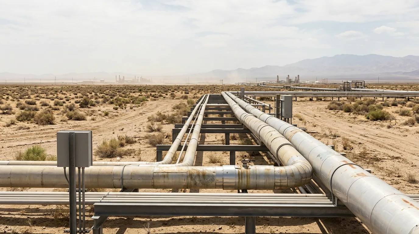
Most aging units carry far more insulated piping and equipment than any team can strip and inspect invasively. A program that opens insulation on a fixed grid wastes scaffolding, insulator hours, and inspector time on circuits that were never going to corrode. It also misses the dead legs, penetrations, and intermittently hot lines where wall loss is concentrated. The result is either a budget that cannot be defended or a leak from a line nobody prioritised. A risk-based CUI program is how you spend a finite inspection budget where likelihood and consequence are both highest.
This article sets out how to build that prioritisation: which temperature conditions to screen for, how to find hot spots, how to judge coating condition, and how to turn the screening into an inspection scope.
Standards and requirements context
The documents below frame the work. Check their current editions against your site's governing inspection procedures.
- DNV-RP-G109 (Risk based management of corrosion under insulation; edition 2025-06) states its objective as a practical and cost-effective risk-based methodology for managing CUI. It is the closest thing to a purpose-built CUI RBI framework.
- API 580 (Risk-Based Inspection) and API 581 (Risk-Based Inspection Methodology) provide the general RBI framework and quantitative methodology that a CUI assessment normally sits inside.
- API 583 (Corrosion Under Insulation and Fireproofing) covers the CUI damage mechanism and its management.
- API 570 (Piping Inspection Code) and API 510 (Pressure Vessel Inspection Code) set the in-service inspection regimes where CUI inspection intervals must be reflected.
- NACE SP0198 (Control of Corrosion Under Thermal Insulation and Fireproofing Materials – A Systems Approach) addresses control of the mechanism through system design.
Published industry work, including papers on using RBI results to justify and manage a CUI program and on RBI practice for both CUI and corrosion under fireproofing (CUF), supports the same logic. Rank by risk, then let the ranking drive inspection scope.
Framing the risk: likelihood and consequence
CUI risk is the product of how likely wall loss is and what happens if the item fails. Treat the two halves separately so that a high-consequence line with weak corrosion drivers is not hidden by averaging.
Likelihood is driven by:
- Operating temperature and its history
- Condition of the coating under the insulation
- Insulation type and its water-retention behaviour
- Weatherproofing and jacketing integrity
- Environmental exposure
- Age of the system
Consequence is driven by:
- Fluid inventory and flammability or toxicity
- Operating pressure
- Proximity to people and critical equipment
- Production dependence on the line
Consequence ratings usually already exist in your RBI database. The CUI-specific work is improving the likelihood side with real data.
Likelihood screening: three filters
Filter 1: operating temperature range
Carbon and low-alloy steels are most vulnerable where metal temperature allows liquid water to be present under the insulation for long periods. That means a band running from below ambient up to somewhat above the boiling point of water. At the lower end, cold and cyclic service pulls in moisture through condensation. At the upper end, water evaporates and concentrates salts and contaminants, which can make attack more aggressive. Well above the boiling range, water seldom persists and carbon steel CUI is generally less likely, though not impossible during shutdowns or upsets.
Austenitic stainless steels are a different problem. Chloride stress corrosion cracking under insulation depends on temperature, chloride availability from the insulation or environment, and tensile stress. Screen these systems separately from carbon steel. Wall-loss inspection methods do not address cracking.
The practical error is using design temperature or normal operating temperature alone. Many lines spend meaningful time outside their nominal range:
- Intermittent service: batch lines and standby spares cycle through the vulnerable band.
- Start-up and shutdown: hot lines spend time cooling and warming through the critical band.
- Heat-traced lines: trace failure or a switched-off trace drops the metal into the wetting range.
- Dead legs and stagnant branches: these often sit well below the main header's temperature and are frequently misclassified.
Guidance on gathering process conditions for RBI makes the same point. The quality of your CUI ranking depends on the quality of the operating-temperature data you feed it. Get actual temperature histories from operations and the historian, not just the P&ID design basis.
Filter 2: hot spots, geometry, and water ingress points
By hot spots I mean locations where water gets in and stays, not just temperature. On aging units the damage is rarely uniform. Prioritise:
- Penetrations and terminations: supports, nozzles, instrument tappings, vents and drains, and insulation termination points at flanges.
- Low points and bottom-of-line sectors: water migrates and pools there.
- Vertical runs below damaged jacketing: water tracks down from the failure point and soaks the sections below it.
- Damaged, unsealed, or deformed jacketing: look for failed sealant, overlaps facing upward, and mechanical damage from foot traffic or maintenance.
- Locations near external water sources: deluge, steam leaks, cooling-tower drift, drips from overhead lines, and washdown areas.
- Pipe supports and shoes: these combine trapped water, crevice geometry, and often coating damage.
A walkdown by an inspector who knows what failed jacketing looks like is worth more than any desktop model at this stage. Photograph and tag what you find, and feed it back into the likelihood score for that circuit.
Filter 3: coating condition and insulation system
The coating under the insulation is the main barrier. Items to establish per circuit include:
- Whether the line was coated at construction, and with what system class
- Whether the coating was specified for the operating temperature, including temperature cycling
- Records of any past stripping and recoating, and whether surface preparation was adequate
- Whether prior inspections found coating breakdown in similar service
Uncoated or poorly coated carbon steel in the vulnerable temperature band is the highest-likelihood combination. Where records are missing, assume the worse case until an inspection window proves otherwise. Do not treat a coating as intact just because no one has looked.
Insulation type matters because some materials hold water longer or release contaminants into it. Record the type, the age, and whether it is original or a patched mix. Mixed repairs often introduce gaps that are not visible from outside.
Turning the ranking into an inspection scope
Once circuits are scored, group them into priority tiers and match inspection effort to the tier. A sensible order of work:
- External screening of all insulated systems in scope. This is a visual survey of jacketing, seals, and signs of staining or leakage. It is cheap and drives the likelihood updates.
- Non-invasive screening on higher-tier circuits. Use profile radiography, pulsed eddy current, or other screening technologies where appropriate. Their effectiveness varies with insulation thickness, jacketing material, and geometry. Qualify the method on your own configurations before relying on it to clear a circuit.
- Targeted insulation removal at selected locations. Choose the hot spots identified above, not a uniform grid. Strip, inspect the bare metal and coating, measure remaining wall, then reinstate with a sound weather seal.
- Feedback. Record findings, including "no damage found", against the specific location and condition. Use them to recalibrate likelihood scores and intervals.
One published treatment of the RBI methodology for CUI describes a structured stepwise approach in which the assessment uses actual operating and structural conditions of insulated equipment. The principle holds regardless of software or framework. Your inputs must reflect field reality, and your outputs must change what the inspection team does.
Safety when opening insulation on live systems
Removing insulation on hydrocarbon-containing equipment is intrusive work even though the pressure boundary is not breached. If the inspection finds significant wall loss, the situation changes quickly. Apply these controls:
- Confirm with operations whether the line can be isolated, depressurised, and verified at zero energy before any intrusive follow-up. Use lock-out/tag-out on the isolation points.
- If removing insulation exposes a suspect area on an in-service line, assess fitness for service before any further mechanical work. Do not strike, grind, or hammer on corroded pipe.
- Treat the work area as hazardous. Use hazardous-area-rated tools and equipment and follow hot-work and permit-to-work rules.
- Use gas detection at the work site, particularly on lines with a history of weeps or leaks, and continue it for the duration of the job.
- Plan safe venting and drainage routes if any line has to be opened for repair. Never vent to an area where people or ignition sources are present.
- Check older insulation for asbestos-containing materials before disturbing it, and follow your site's hazardous-material procedure.
Illustrative example
This scenario is illustrative, not drawn from a specific site or published case.
An aging process unit has three insulated carbon steel circuits that the RBI database ranks identically because they share a design temperature.
- Circuit A is a continuously hot header, operating well above the water-boiling range. The coating is intact on record and the jacketing is in good condition.
- Circuit B is an intermittently used transfer line that cycles through the vulnerable range. It has an unrecorded coating history, sits under a leaking deluge header, and has several damaged jacketing sections above a pipe shoe.
- Circuit C is a dead-leg branch off a hot header. Its fluid is stagnant, its metal temperature sits in the wetting range, and it is lightly insulated with weathered sealant.
A uniform grid would give each circuit the same inspection effort. Risk-based screening changes that. Circuit B and Circuit C move to the top of the inspection list. Both combine a vulnerable temperature band, poor or unknown coating, and visible water ingress. If B also carries flammable fluid near a walkway, its consequence rating raises it further. Circuit A drops to a lower tier, with external survey only, until something changes. The same inspector-hours produce far more information about real damage, and the reasoning is documented for the next review.
Checklist for building the program
- Define the scope: which insulated systems, which materials, and whether fireproofing is included.
- Gather actual operating temperature histories, including start-up, shutdown, standby, upset, and trace-failure conditions.
- Flag intermittent-service lines, dead legs, and heat-traced lines for specific review.
- Separate carbon and low-alloy steel wall-loss screening from austenitic stainless cracking screening.
- Record coating history and condition per circuit, and treat unknown as unfavourable.
- Walk down jacketing and sealing condition, and photograph and tag damaged areas.
- Identify penetrations, supports, terminations, and low points on each circuit.
- Check for external water sources above or near insulated lines.
- Rate consequence using your existing RBI data, and review it for CUI-specific escalation, such as proximity to personnel.
- Qualify any non-invasive screening method on your insulation and jacketing configuration before using it to clear a circuit.
- Select strip locations from the hot-spot list, not from a uniform grid.
- Write permit, isolation, gas-detection, and hazardous-material requirements into the work pack.
- Log all findings, including negative ones, and update likelihood scores and intervals.
- Reinstate insulation with sound weatherproofing, and record the repair.
Conclusion
A CUI program that ranks circuits by real operating temperature exposure, water ingress points, and coating condition makes better use of the same inspection resources. It also gives you a defensible basis for the scope.
For your next step, pick one aging unit and collect actual temperature histories and jacketing condition for its insulated circuits. Re-rank them against the three filters above and compare the result with your current inspection plan. Where the two disagree, you have found your first priorities. Then align the resulting plan with your site's inspection program and the framework in DNV-RP-G109, and feed every inspection result back into the ranking.