Turret-moored FPSOs in harsh environments tend to fail in a few recognisable ways. The turret bearing gets loaded past what the hull and its support structure were built for. A mooring line breaks, and the survivors can't take the load that gets shoved onto them. Or the vessel stays connected through a storm it should have left. Each of these ends badly: unplanned shutdown, riser damage, or loss of station. You can't bolt a turret onto a finished hull, so the mooring layout, riser array, bearing arrangement, and disconnect philosophy have to be settled together, and early.
This article gives mechanical and structural engineers a design-level view of those linked choices. It draws on the research sources listed at the end and on established practice.
Standards and requirements context
Turret and mooring design falls under stationkeeping and floating-production standards. There isn't one dedicated turret standard. The documents you'll see cited most are:
API RP 2SK, Design and Analysis of Stationkeeping Systems for Floating Structures, which covers mooring analysis, line tension limits, and intact and damaged conditions.ISO 19901-7, Stationkeeping systems for floating offshore structures and mobile offshore units, the international counterpart for mooring design and analysis.API RP 2FPS, Planning, Designing, and Constructing Floating Production Systems, which covers the whole floating production system, including the vessel, mooring, and riser interface.
Classification societies layer on their own rules for turret structure, bearings, and position mooring. Operators usually add project specifications on top. Pin down the edition and acceptance criteria that apply to your project, and talk to the certifying authority early about how disconnectable operation will be classified. Intact, damaged (one line lost), and transient conditions are all design cases. Each load combination drives the sizing of the bearing and structure.
Why the turret is the design driver
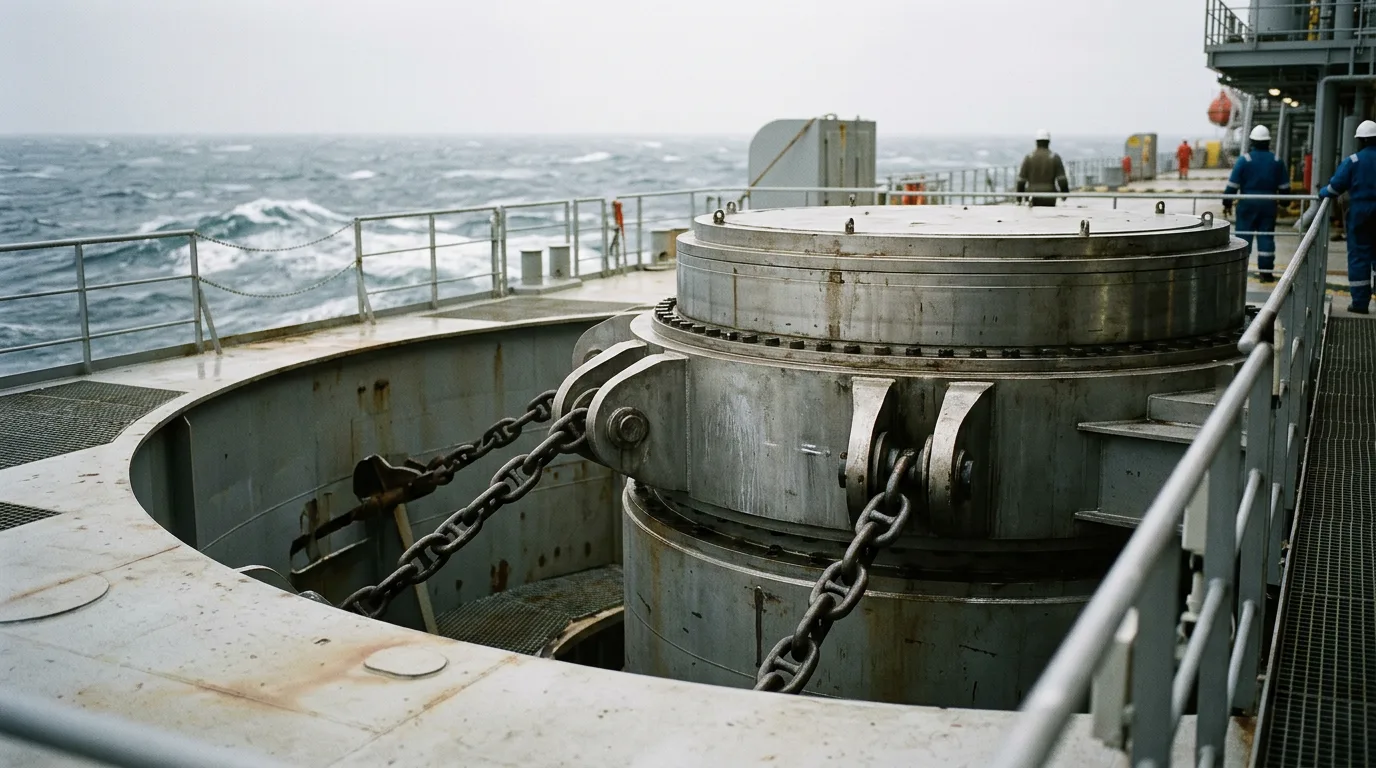
The turret lets the vessel weathervane while the mooring lines stay fixed to the seabed. The bow swings into the dominant environment, which cuts the loads the mooring has to resist. At harsh sites that benefit is big, and it's why the turret gets called critical for harsh weather. The price is that every mooring and riser load runs into the hull through a rotating interface.
The central point still holds. Mooring, turret structure, bearing, and hull have to be analysed as one coupled load path. Don't treat them as separate packages.
Turret bearing loads
Load components
The bearing and its supporting structure see a combination of actions:
- Horizontal mooring load. The horizontal components of line tension add up and react as radial load on the bearing.
- Vertical load. Turret self-weight, vertical line tension components, riser and umbilical hang-off loads, and the swivel stack's weight where the turret carries it.
- Overturning moment. Mooring and riser loads act at a different elevation from the bearing plane, so the bearing takes a moment on top of radial and axial force. In a harsh sea state this moment is often what governs the roller arrangement.
- Dynamic and inertial effects. Vessel motion puts inertial loads on a big rotating mass. The turret never stops seeing oscillating load.
Hull interaction
Hull deformation is the part people underestimate most. A ship-shaped hull flexes under wave bending and as cargo and ballast move around. The bearing has to hold its allowable geometry through all of those cycles. In design, check:
- Race flatness and roundness under hull girder deflection, not just in still water.
- Stiffness of the turret-to-hull support structure. Local flexibility shifts how load gets shared across the bearing rollers.
- Fatigue in the turret-to-hull connections, which cycle in every sea state.
- Fabrication and installation tolerances. Alignment errors eat into the bearing's margin against extreme load.
Bearing and swivel arrangement
Bearing type (multi-row roller, tapered roller, or spherical roller) is a trade between load capacity, tolerance of deformation, and maintainability. Whichever you pick, design in access to inspect and swap wear parts, and room for the drive or brake that controls rotation.
The swivel stack is its own failure path. It carries fluid across the rotating interface, so seal work on it means handling hydrocarbon-containing equipment. Any job on the swivel follows the full isolation sequence: isolate, depressurise, verify zero energy, apply LOTO, control ignition sources in the hazardous area, run continuous gas detection, and vent to a safe location.
Mooring layout choices
Spread versus turret
Spread mooring, with lines attached along the hull, is the traditional alternative. Without a turret the vessel can't weathervane. It takes environmental loads from whatever direction the lines have fixed it at. Where weather is variable and severe, that's a heavy penalty, and a turret is usually the favourite. If one direction dominates and the field is simple, spread mooring can still compete. The turret brings the cost and complexity of the rotating interface with it.
Line grouping and redundancy
Turret lines are usually grouped around the turret circumference. The points that matter most:
- Load sharing after a line failure. The layout has to survive the loss of one line without neighbours failing in sequence. This is a standard check in the stationkeeping standards.
- Directional bias. If extreme weather has a dominant direction, group orientation and stiffness distribution can be tuned to it, as long as the off-direction cases still pass.
- Riser clearance. Line corridors and riser corridors fight over the same seabed and water column. Assess clash risk in both intact and damaged conditions.
- Fairlead and chain stopper loads. At the stopper, lines pass high tension and angular motion into the turret. That's a fatigue-sensitive spot, so chain wear and bending there need explicit inspection planning.
Riser arrays drive turret design
Every extra riser or umbilical means another hang-off position, a bigger turret and swivel stack, more load, and tighter coordination with the mooring lines. Water depth, vessel purpose, and environment are the core variables. Modern harsh-environment designs have to fit complex multi-riser arrays inside the hull. If the field plan might add risers later, decide up front whether the turret gets spare slots.
Disconnect versus weathervane-only
What is being decided
A permanently connected turret weathervanes through the design storm and stays on station. A disconnectable system lets the vessel leave, leaving the mooring and risers on a buoy, and come back later.
Comparison
| Aspect | Permanent weathervane turret | Disconnectable turret or buoy |
|---|---|---|
| Extreme-event strategy | Resist the full design storm connected | Leave the site before the extreme event |
| Structural sizing | Bearing, turret, and mooring sized for the full extreme load | Connected-case loads reduced, but the buoy and connector add their own design cases |
| Mechanical complexity | Fewer moving interfaces | Connector, latching, buoy, and reconnection systems added |
| Riser system | Risers remain connected and hung off at the turret | Risers must be designed for the disconnected state and for repeated connect cycles |
| Operational risk | Station-keeping margin must hold for the whole event | Risk shifts to the disconnection and reconnection operations |
| Production | Continuous unless the storm forces shutdown | Production lost while disconnected, plus the recovery time |
| Best fit | Severe but manageable environments, long-term continuous operation | Sites with events that make staying connected uneconomic or unsafe |
Design issues specific to disconnectable systems
- Buoy behaviour when disconnected. The buoy, mooring, and risers need to be stable, with acceptable motions, clearance, and riser loads while the vessel is away.
- Reconnection loads. Contact between buoy and vessel receiving structure in residual sea states is its own load case, and it sets the operational weather window for reconnection.
- Emergency disconnect. A fast disconnect still has to isolate and secure hydrocarbon-carrying risers safely. The sequence has to be engineered, tested, and rehearsed.
- Fatigue and wear. Repeated connection cycles change the fatigue and wear picture for connectors and guides.
Illustrative scenario
The following is a constructed example, not a real project.
An operator plans an FPSO at a remote site where the extreme storm is far more severe than typical operating weather. Two concepts go head to head: a permanent internal turret and a disconnectable buoy turret.
For the permanent turret, the analysis shows the overturning moment on the bearing in the extreme storm governs. Meeting it means a stiffer turret support structure and a larger bearing. The damaged case (one line lost) also governs line sizing. The project team accepts higher steel and bearing cost to keep production continuous.
For the disconnectable concept, the connected design storm is milder, which takes pressure off the bearing and the lines. Then the team finds that the riser system has to be designed for the disconnected condition, and that the reconnection weather window sets the production uptime. The real question becomes whether the cumulative time disconnected, plus the risk from each connection operation, is acceptable.
The answer depends on how often the site actually forces a departure, and on whether the permanent turret can be designed with credible margin. Compare the two on structural margin, operability, and risk, using the site's metocean data. Don't settle it with a rule of thumb.
Decision checklist
- Define the extreme and operating environments, including dominant directions and how persistent they are, before choosing turret type.
- Confirm the load path from line to seabed anchor through the turret, bearing, and hull, and analyse it as one coupled system.
- Check bearing geometry under hull deformation in all loading conditions, not just still water.
- Treat overturning moment as a primary bearing load case, not a secondary one.
- Verify intact, one-line-lost, and transient cases against the applicable stationkeeping standard.
- Coordinate the riser array and mooring corridors, including clash in damaged conditions.
- Decide early on spare riser slots and future tie-ins, because the turret can't easily grow later.
- Identify fatigue-critical locations: chain stoppers, fairleads, turret-to-hull connections, and the bearing.
- If considering disconnection, define the reconnection weather window, emergency-disconnect sequence, and buoy behaviour while disconnected.
- Plan inspection access for bearing, drive, swivel, and stoppers during the design phase.
- For swivel and riser-related work on hydrocarbon-containing equipment, apply the full energy isolation sequence: isolate, depressurise, verify zero energy, apply LOTO, control ignition sources in the hazardous area, run continuous gas detection, and vent to a safe location, in accordance with the applicable process safety and maritime regulations for the jurisdiction.
- Agree class and certification requirements for the disconnectable system with the authority at the start.
Conclusion
On a harsh-environment FPSO, the turret, mooring, and riser array behave as one system, with the bearing at the centre of it. Carry overturning moment and hull deformation as primary bearing cases, and size the mooring for damaged conditions as well as intact ones. The permanent-versus-disconnectable choice comes down to structural margin on one side and the operational and safety cost of leaving and returning on the other.
Next, gather the site's metocean data and riser plan, run both concepts through the coupled analysis required by API RP 2SK or ISO 19901-7, and take the results to the certifying authority before the hull and turret design is locked.