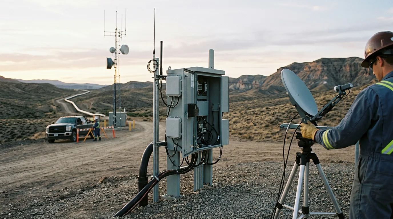
Offshore platforms usually run telemetry over a patchwork: wired field networks, point-to-point radios, and one satellite or microwave link carrying everything to shore. When that patchwork fails, the effects are practical. Operators lose sight of remote wellhead and utility skids, and inspection rounds go back to being manual. Contractors can't reach remote experts. A single backhaul fault can cut the SCADA historian off from the onshore control room. Private LTE and 5G promise one managed radio layer for sensors, handhelds, cameras and control traffic. Getting that to work inside a congested steel structure comes down to three decisions: how coverage is designed, how the platform connects to shore, and where the radio network meets the control system. Mistakes in any of them are expensive to fix once the cell sites are up.
Standards and requirements context
Few standards govern a private cellular network on a platform directly. The relevant requirements come from adjacent disciplines:
IEC 61511covers functional safety of safety instrumented systems in the process industry. Cellular links should not be placed inside a safety function unless the safety case explicitly justifies it. The default approach is to keep trip and shutdown logic hard-wired or on dedicated safety networks and use cellular for monitoring, diagnostics and non-safety control.IEC 62443covers security for industrial automation and control systems. It supplies the zone-and-conduit model for placing the radio core, the user plane break-out and the SCADA gateways.IEC 60079-0sets the general requirements for equipment in explosive atmospheres. Every antenna, radio unit, handset and enclosure installed in a classified area needs appropriate certification for that zone. The area classification drawing governs where radio hardware can physically go.IEC 62541defines OPC UA, the most common vendor-neutral way to present field data to higher-level systems.
Spectrum licensing, maritime flag-state rules and coastal-state requirements also apply, and they vary by jurisdiction. Settle them early. They decide which spectrum you can use.
The research shows the same pattern. The list above helps with scoping, because each use case tolerates outages differently.
Radio planning inside steel structures
Why platforms are hostile to RF
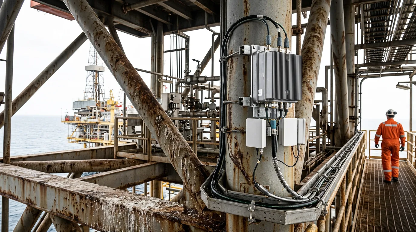
A platform is packed with steel: decks, modules, pipework, cable trays, tanks and process vessels. Signals bounce, diffract and get blocked. Coverage that looks fine in free space can vanish behind a separator module or inside a pump room. Wind platforms are a different class of structure, but the steel-structure propagation problem is the same.
In practice, expect the following:
- Strong multipath, with signal level swinging sharply over short distances.
- Deep shadowing behind modules, inside enclosed rooms, and below decks.
- Reflections from the sea surface and from adjacent structures such as flare booms, cranes and neighbouring platforms.
- Blockage that comes and goes, from cranes, supply vessels and moving equipment.
Design approach
Don't plan from drawings alone. A workable sequence:
- Build a 3D model from the structural and layout drawings, including the main steel, module walls and major vessels.
- Run a walk-through survey with a test transmitter to calibrate the model, especially in enclosed rooms and under-deck areas.
- Place a small number of macro or small cells for open decks and the sea approach. Then add distributed antennas or low-power radio heads for enclosed spaces, stairwells, laydown areas and the accommodation block.
- Re-run predictions using the actual mounting positions, since the hazardous-area drawing often moves antennas away from the preferred locations.
- Validate after installation with drive-walk measurements, and record the baseline coverage and throughput maps for later comparison.
Design for the demanding job, not for average coverage. A handheld gas detector or a camera on a remote drone landing pad needs reliable signal at its actual location, not a percentage of deck area covered. Set coverage requirements per asset class: fixed sensors, mobile workers, vehicles and drones, and CCTV.
Plan uplink capacity on purpose. Video and inspection data are uplink-heavy, but default cellular configurations lean toward downlink. Check the uplink/downlink split against sensor and camera traffic.
Core placement and edge compute
Keep the core local. If it sits onshore, a backhaul outage takes authentication and the whole radio network down with it. Process traffic on the installation itself. Whatever the vendor, the principle holds: the local core must keep working in island mode, with local authentication, local user-plane break-out and local DNS and time services. On-platform devices then keep communicating when the link to shore is lost. Offshore Magazine's 2025 coverage of Tampnet makes the related point that a private 5G network can connect devices and sensors across the entire installation. That scope makes local survivability matter more, because more operations depend on the network.
Backhaul: satellite, fibre and microwave
Backhaul decides what the platform can do when sea state, a passing vessel or an outage works against you. The options differ in character more than in headline numbers, so choose by failure mode and service need.
| Criterion | Subsea fibre | Microwave / offshore radio link | Satellite (GEO or LEO) |
|---|---|---|---|
| Capacity growth | Highest headroom | Moderate, depends on spectrum and link design | Constrained by service plan and terminal |
| Latency | Lowest and most stable | Low, depends on hop count | Higher, varies with orbit type |
| Weather sensitivity | Immune | Affected by heavy precipitation and path obstruction | Affected by heavy rain, antenna blockage and platform motion |
| Typical failure mode | Cable damage, often slow to repair | Alignment loss, path blockage, equipment faults | Terminal or antenna faults, obstruction by structure |
| Lead time and cost | Long, capital-intensive, route-dependent | Moderate | Fastest to deploy, with operating-cost exposure |
| Best use | Fixed, data-heavy platforms near infrastructure | Platforms within reach of shore or neighbouring installations | Remote or temporary installations, and diverse backup |
Several decisions follow from the table:
- Treat diversity as a requirement. Fibre plus satellite, or microwave plus satellite, gives independent failure modes. Two links sharing a single physical path or a single terminal location are not diverse.
- Prioritise traffic. Classify SCADA polling, voice, safety-related alerts, CCTV and bulk data separately. Apply quality-of-service policies at the edge so that a degraded backup link carries only what matters.
- Size the backup for minimum operating service. It should carry control-room visibility, voice and critical alarms, not full video archives.
- Place satellite antennas with the radio plan. Blockage of satellite terminals by structure and cranes is a platform layout problem. Treat it as a design issue, not a communications fault to fix later.
Integrating field telemetry into the plant network
Architecture
Use the zone-and-conduit approach from IEC 62443. The radio access network, the private core and the user-plane break-out sit in a defined zone. A firewall or data diode-style gateway controls the conduit to the control network. Field devices on cellular should reach SCADA through a defined path, not through a flat network shared with business IT and visitors' devices.
Data path
Most field telemetry uses fieldbus or serial protocols at the instrument layer. A practical pattern:
- Sensors, RTUs or protocol gateways connect over the cellular link.
- A local gateway converts data to a standard interface such as OPC UA (
IEC 62541), or to the protocol the SCADA already polls. - SCADA treats the cellular-connected points like any other source, with quality flags and timestamps preserved.
- Store-and-forward at the gateway buffers data during a backhaul outage, so the historian can be back-filled once the link returns.
Check how the SCADA driver handles communication loss and late data. A polling driver that times out and marks values bad is acceptable. One that silently holds the last good value is a hazard.
Safety boundaries
Under IEC 61511, keep safety instrumented functions independent of the radio layer. Cellular suits condition monitoring, wireless gas and instrument readings for operator awareness, worker location and inspection data. It should enter a safety function only through a documented assessment, with its failure behaviour defined.
Security
Use SIM or certificate-based device authentication, segment device classes, and control who can add new devices to the network. Apply patching and change management to the radio core with the same discipline you'd apply to a controller. Keep an inventory of every connected device.
Illustrative scenario
This scenario is illustrative and not drawn from a named project. A normally attended platform has a wellhead module, a process module and an accommodation block. It also has a fibre link to shore, with a satellite terminal as backup. The operator wants wireless vibration and corrosion sensors on rotating equipment, handheld devices for operators, and camera coverage of the helideck and laydown area.
The survey shows good open-deck coverage from two mast-mounted cells but poor coverage inside the compressor enclosure and under the process module. The design adds distributed radio heads in those areas, positioned according to the hazardous-area drawing. The core is installed on the platform, so devices keep authenticating when the fibre is cut. A gateway converts sensor data to OPC UA for the existing SCADA, with store-and-forward buffering. Quality-of-service rules ensure that when traffic fails over to satellite, alarms, voice and SCADA polling get through while camera archives wait. Shutdown logic stays hard-wired and is untouched. The acceptance test is a fibre-disconnect trial. It should show on-platform services continuing, backup traffic prioritised correctly, and buffered data recovered afterwards.
Checklist and decision guidance
- Define use cases and the outage tolerance of each before choosing an architecture.
- Confirm spectrum availability and regulatory approval for the platform's location and flag.
- Build a 3D propagation model and calibrate it with a walk-through survey.
- Specify coverage per asset class and per location, including enclosed rooms and under-deck areas.
- Check that the uplink/downlink configuration suits video and sensor traffic.
- Verify hazardous-area certification for every radio component against the classification drawings.
- Place the core on the platform and test island-mode operation.
- Choose backhaul paths with independent failure modes, and confirm the physical separation.
- Define traffic priorities and test them on the backup link.
- Keep safety instrumented functions independent of the cellular network, consistent with
IEC 61511. - Apply zone-and-conduit segmentation and device authentication from
IEC 62443. - Confirm SCADA behaviour on data loss, late data and quality flags.
- Record baseline coverage and performance maps at handover for later comparison.
- Plan for spares, remote monitoring of the radio network, and a named owner for ongoing changes.
Conclusion
A private cellular network on a platform lives or dies on the unglamorous parts: a calibrated propagation model, a core that survives loss of the shore link, backhaul with independent failure modes, and a clean boundary between the radio layer and the control and safety systems. Start with a register of use cases and outage tolerances, commission a survey-based coverage design, and run a backhaul-failure trial as a formal acceptance test. Then migrate non-safety telemetry in stages, proving each stage against how the SCADA behaves under communication loss before moving on.