Subsea power distribution in the Arctic is a reliability problem before it is an electrical design problem. A subsea tieback that relies on a long-distance power feed, subsea transformers, switchgear, and wet-mate connectors has few ways to recover once ice, weather windows, and vessel availability limit intervention. One unplanned outage can mean deferred production, a mobilisation that cannot happen for months, and a restart under degraded conditions. The OTC paper Power Distribution for Arctic Subsea Tiebacks (2012) puts the driver plainly: tiebacks are becoming more common, and wellheads are getting harder to reach. So power architecture has to be judged by what can be recovered, not only by what can be built.
This review covers how to structure a risk assessment for these systems, which failure modes deserve the most attention, and how to turn the results into maintenance and procurement decisions.
Standards and requirements context
The standards below are the ones I am confident apply. None of them replaces project-specific design basis work.
- SEPS SP-1005, Subsea Electrical Power System Design Requirements (first issue, March 2024). An industry-joint-project specification for subsea electrical power systems. Use it as the baseline for system integration and design requirements. Check its scope and normative references against your contract.
- ISO 19906 covers Arctic offshore structures. It sets the environmental and ice-action basis that topside and host-facility assumptions must be consistent with.
- ISO 13628-6 covers subsea production control systems. It matters where power and control are integrated or share umbilical infrastructure.
- IEC 61511 covers functional safety for safety instrumented systems in the process industry. It applies where electrical protection or isolation is credited as a safety function. It does not apply to general power protection.
- IEC 60812 describes FMEA/FMECA technique and is the usual basis for the failure-mode work below.
- ISO 14224 covers collection and exchange of reliability and maintenance data for equipment. Use it to structure failure records so field data can feed back into the assessment.
- ISO 31000 gives guidelines on risk management. It supplies the process framework: context, identification, analysis, evaluation, treatment, and monitoring.
What makes the Arctic different
Environmental and logistical drivers
The review Offshore system safety and operational challenges in harsh Arctic operations (Journal of Safety Science and Resilience, 2022) covers the safety and operational burdens of Arctic offshore work. For a subsea power system, those burdens show up as four practical problems:
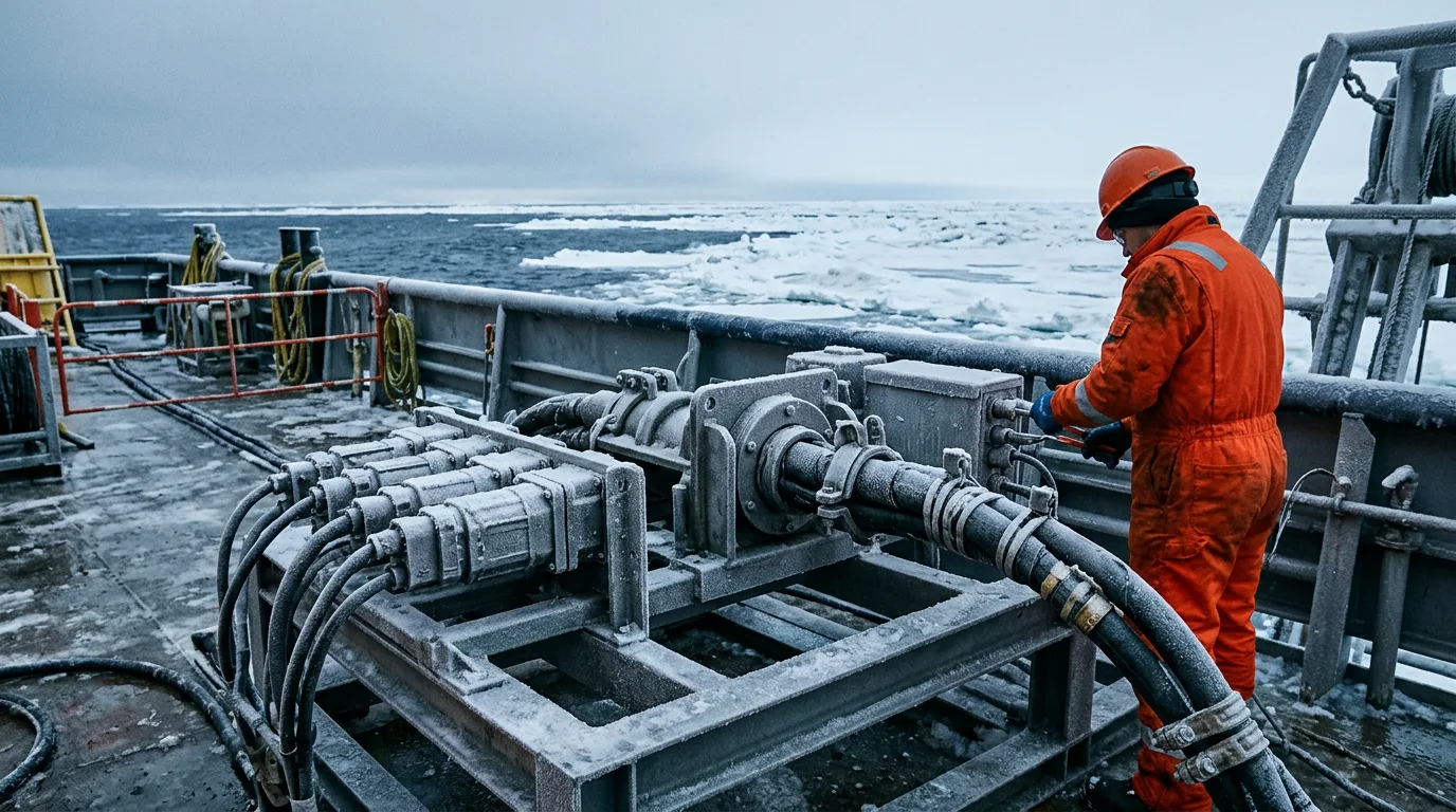
- Intervention is intermittent. Remote location, limited vessel support, and seasonal ice cut the number of usable intervention windows. Any failure that needs a vessel is effectively a long-duration failure.
- Topside constraints are tighter. Cold, icing, and a thin crew affect the host or onshore power source, the variable speed drives, and the topside end of the umbilical.
- Ice interaction reaches the seabed. In shallower Arctic water, ice features can threaten exposed cable, protection structures, and landfalls. The ISO 19906 environmental basis should drive the burial and protection philosophy.
- Response capability is thin. Emergency response, spares, and specialist people are all farther away, so every failure mode carries more consequence.
The 1994 Office of Technology Assessment report Power Sources for Remote Arctic Applications is dated, but its core point still stands. In remote Arctic settings, power source cost and reliability cannot be separated from logistics. A source that is cheap to buy but hard to service is not cheap.
Security and third-party interference
For a reliability engineer, this adds a low-frequency, high-consequence scenario: cable and landfall damage. It belongs in the risk register even though it sits outside normal environmental design cases.
Failure modes that deserve the most attention
The table ranks qualitatively. It is a starting point for a facilitated FMEA session, not a substitute for one, and it deliberately carries no failure rates. Populate rates from your own operator data or from ISO 14224-structured sources.
| Subsystem | Dominant failure mechanisms | Why it matters in the Arctic | Primary mitigation lever |
|---|---|---|---|
| Dynamic/static power umbilical or cable | Insulation degradation, water ingress, mechanical damage from ice or trawl-type interaction, fatigue at hang-off | Repair needs a vessel and a suitable weather and ice window | Route and burial design, protection, monitoring of insulation condition, spare cable strategy |
| Subsea transformer and VSD-related equipment | Thermal ageing, dielectric fluid or compensation system faults, partial discharge | Cannot be inspected; failure is usually a retrieval event | Conservative loading, condition monitoring, qualification evidence |
| Subsea switchgear and protection | Contact wear, actuator faults, enclosure leakage, protection maloperation | Spurious trips are costly where restart needs coordination across a long tieback | Protection coordination study, redundancy, design for diagnosability |
| Penetrators and wet-mate connectors | Seal degradation, contamination during mating, insulation tracking | Connector intervention is among the hardest to schedule | Qualification, installation procedure control, mating inspection |
| Topside power and drives | Cold-start issues, icing, ventilation and heating failures, harmonics | Harsh topside conditions with limited maintenance staff | Winterisation, heat-trace and enclosure design, remote diagnostics |
| Control and communication | Common-cause loss of power supply to control, signal degradation | A loss of visibility turns a minor fault into a blind shutdown | Independent supplies, diagnostic coverage, defined fail-safe states |
Common-cause failure
Redundancy on paper can collapse into a single failure. That happens when both paths share a cable corridor, a topside bus, a control power source, or one installation event. In Arctic tiebacks, the common-cause questions that matter most are:
- Do redundant feeders share a route that one ice or seabed event could damage?
- Do protection and control functions depend on the same auxiliary power source?
- Were redundant components installed, tested, and commissioned under the same procedure, so that one error gets copied to both?
- Can a single topside event, such as a utility loss or icing of a shared enclosure, take out every path at once?
Electromagnetic and interaction effects
The Utsira High Power Hub study shows that high-power offshore distribution hubs raise electromagnetic considerations that have to be assessed in the design phase. For reliability work, the concern is interaction. Fields from high-current cables can influence nearby instrumentation, cathodic protection, or other cables. Screen these interactions at design stage, not during commissioning.
Building the risk assessment
Step 1: Define the consequence in operational terms
Describe each failure by what it does to the field, not only to the equipment. Typical consequence classes are loss of one consumer, loss of a power train, loss of the whole tieback, and loss of control visibility. Add a recovery dimension too: recoverable from the host, needs a light intervention vessel, or needs retrieval of a subsea module.
Step 2: Use a barrier model for the causal logic
Structure the causal logic as a barrier model, with operational databases used to quantify events. Put the top event, for example loss of subsea power to the tieback, in the centre. List threats on the left and place preventive and recovery barriers on the right. Then ask of each barrier whether it can be tested, whether it depends on another barrier, and whether anyone owns it.
Step 3: Rank by recoverability as well as likelihood
A frequent failure that can be fixed from the host may matter less than a rare one that needs retrieval during ice cover. Rank by likelihood, consequence, and time to restore together. Keep the ranking criteria in your risk framework, in line with ISO 31000. Do not invent universal thresholds for them.
Step 4: Link barriers to monitoring
For each credited barrier, define the measurement that shows it is still working. Examples include insulation resistance trends, partial discharge activity, temperature trends against commissioning baselines, protection event logs, and communication health. Alarm limits belong in the project's design basis and supplier data, not in a general article.
Illustrative scenario
This scenario is constructed for guidance and does not describe a real project.
A tieback is fed by a single power umbilical from a host facility, with two subsea transformer trains supplying separate consumer groups. The design shows redundancy: either train can carry the essential load. During the FMEA, the team applies the common-cause questions above and finds three issues:
- Both trains share one auxiliary control power supply from the umbilical.
- Both trains' switchgear actuators were installed under one procedure, with one inspection signature.
- The umbilical has a single route over the section where seabed ice interaction is credible.
The team's actions follow the recoverability ranking:
- The auxiliary supply is split into independent paths, each with a defined fail-safe state.
- The installation procedure for the second train gets an independent verification step.
- The umbilical route issue cannot be removed after installation. So the team sets up condition monitoring for the exposed section, holds a pre-agreed repair plan, and identifies which spare cable and vessel would be needed.
The result is not a number. It is a documented change in how each failure gets recovered. The single-umbilical exposure becomes a managed residual risk with a named owner, instead of an unexamined assumption.
Checklist for reliability engineers and procurement
- Confirm the environmental and ice design basis is consistent with ISO 19906 and applies to every element, including landfalls and topside.
- Build the FMEA to IEC 60812 and record failure data in an ISO 14224-compatible structure so operating experience feeds back.
- Map every credited barrier to a measurable health indicator and a named owner.
- Check redundant paths for shared routes, shared auxiliary supplies, shared procedures, and shared topside dependencies.
- Rank risks by likelihood, consequence, and time to restore, using the criteria in your ISO 31000 framework.
- Require qualification evidence for subsea transformers, penetrators, and wet-mate connectors under conditions matching the intended duty. Ask suppliers how each design supports diagnosis without retrieval.
- Check the design against SEPS SP-1005 for subsea electrical power system integration, and document any deviations.
- Where electrical isolation is a safety function, assess it under IEC 61511 and not only as a protection relay setting.
- Include cable and landfall interference, deliberate or not, in the risk register.
- Review EMF and interaction effects at design stage, as the Utsira High Power Hub study illustrates.
- Plan spares, vessel access, and repair logistics for the ice season before first power.
- For topside or onshore work on power equipment, require documented energy isolation, lockout/tagout, verification of dead state with a proving test, hazardous-area controls where the area is classified, and gas detection where hydrocarbons could be present.
Conclusion
In Arctic subsea power distribution, recoverability matters as much as reliability. The most useful risk assessments name failure modes, trace their causes through a barrier model, and rank them by how hard they are to fix, not just by how likely they are. Check redundancy for common-cause weaknesses, tie barriers to monitoring, and treat cable exposure and logistics as design inputs.
Next, run a facilitated FMEA against the design basis and review the results against SEPS SP-1005. Write the recovery plan for each high-ranking failure before the design is frozen. Ask suppliers for diagnostic and qualification evidence, not just compliance statements.