Sizing Pressure Safety Valves for Gas-Filled Vessels Under Fire Case
Incorrect classification of vessel surface area during fire-case sizing creates immediate operational risk. If a gas-filled vessel is assessed using wetted area methodology, the calculated heat input will be underestimated. This leads to an undersized pressure safety valve (PSV). During a pool fire, the vessel wall temperature rises rapidly without the cooling benefit of vaporizing liquid. If the relieving capacity cannot match the gas expansion and metal weakening, the vessel may rupture before the valve opens fully. Conversely, overestimating the unwetted area leads to oversized valves, causing procurement waste and potential stability issues during minor relief events. Process engineers must distinguish between wetted and unwetted surfaces to ensure the relief system matches the physical failure mode defined in API 521.
Standards and Requirements Context
The primary governing document for this calculation is API 521, titled Pressure-relieving and Depressuring Systems. The seventh edition, published in June 2020, outlines the methodology for determining heat absorption during fire exposure. This standard differentiates between vessels containing liquid and those containing only gas or vapor. For the mechanical sizing of the valve itself, engineers reference API 520, which provides the formulas to convert heat input into required relieving area.
Compliance with these standards is not merely regulatory; it addresses the physical limits of the vessel material. Research indicates that rupture occurs when the applied stress exceeds the yield or ultimate tensile strength of the material at the elevated temperature reached during fire exposure. Therefore, the sizing calculation must accurately reflect the thermal load on the vessel wall.
Technical Body: Wetted vs Unwetted Methodology
The core distinction in fire-case sizing lies in how the vessel wall absorbs heat from an external fire. The methodology changes based on the fluid level inside the vessel at the time of the incident.
Heat Absorption Mechanics
When a vessel is wetted, liquid covers the internal surface of the shell. During a fire, heat transfers through the metal wall into the liquid. The liquid absorbs this energy as latent heat of vaporization. This phase change keeps the metal wall temperature relatively low, preserving the tensile strength of the steel. The heat input equation in API 521 accounts for this by applying a specific factor to the wetted surface area.
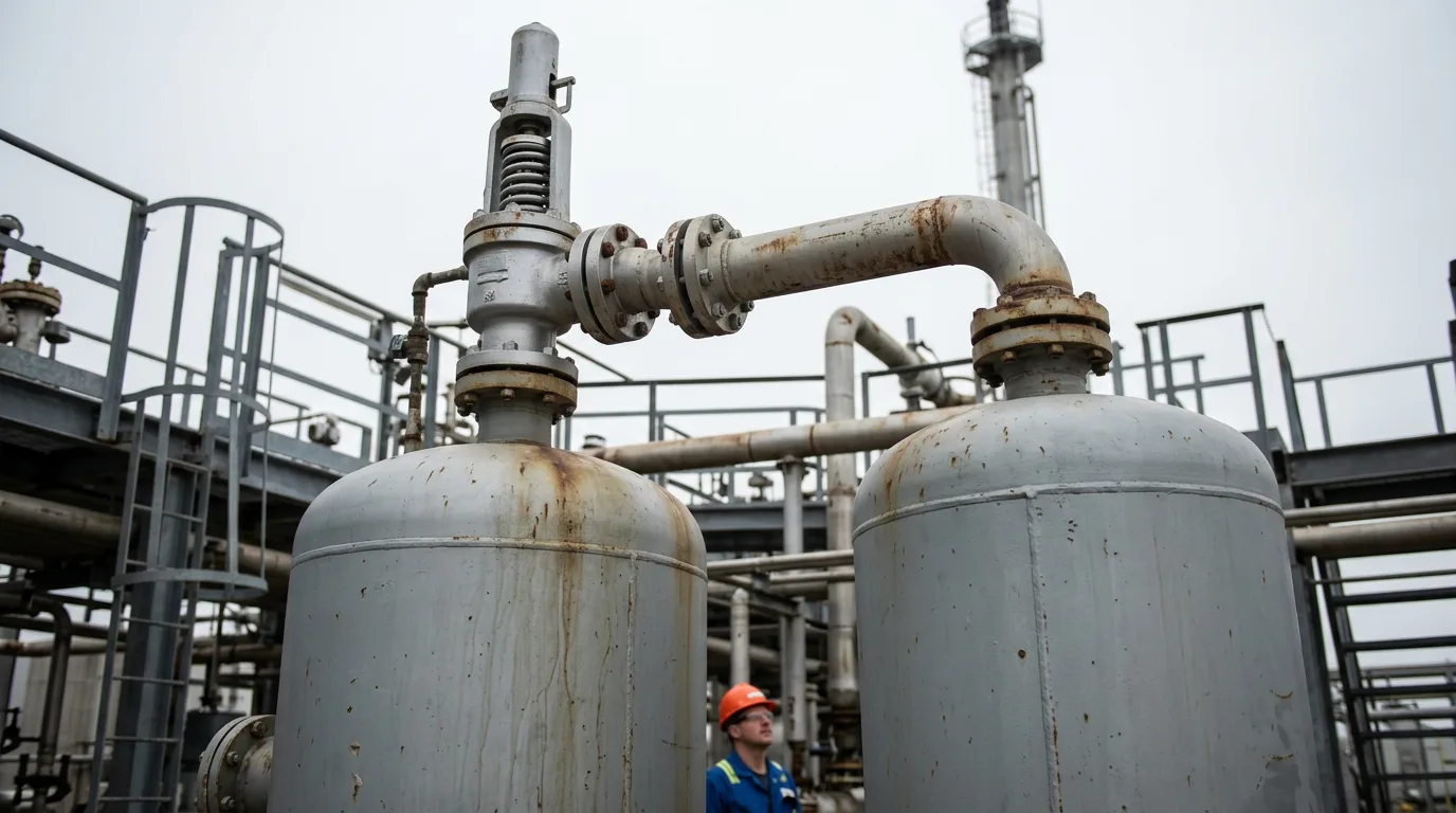
When a vessel is unwetted, such as a gas-filled compressor knockout drum or a surge vessel, there is no liquid to absorb the heat. The fire impinges directly on the metal. The wall temperature rises quickly, reducing the yield strength of the material. The API 521 methodology requires a different calculation approach for unwetted areas to account for the lack of cooling. The heat input is generally higher per unit of area compared to wetted surfaces because the metal temperature is not capped by the boiling point of the liquid.
Determining the Exposed Area
Calculating the correct surface area is the most critical step. For vertical vessels, the wetted area is typically calculated up to a specific height from the ground or grade, often limited by the potential flame height. For unwetted vessels, the entire exposed surface area contributes to the heat load.
For fire case calculations, the total exposed surface area includes the shell and the exposed heads. If the vessel is elevated, the area below the support structure may not be exposed to the fire, depending on the fuel source location. However, conservative design usually assumes full exposure unless specific fireproofing or drainage mitigates the risk.
The Environment Factor
The heat input equation utilizes an environment factor, often denoted as F. For bare, uninsulated vessels exposed to fire, API 521 specifies F = 1.0. For insulated vessels, F is reduced based on the insulation material and fire-resistance rating, provided the insulation remains intact during the fire scenario. Engineers must verify the insulation specification against API 521 requirements before applying a reduced factor. For insulated vessels, the factor reduces the heat input, provided the insulation is fire-resistant and remains in place during the fire. Engineers must verify the insulation specification against the API 521 requirements for credit to be taken. If the insulation is not fire-proofed, the vessel must be sized as bare.
Illustrative Worked Example: Area Calculation
The following scenario is illustrative. It demonstrates the geometric difference between wetted and unwetted area calculations for a vertical vessel. All dimensions are hypothetical for calculation demonstration.
Scenario: A vertical separator vessel is installed in a production facility. The vessel has a tangent-to-tangent length of $10$ meters and a diameter of $2$ meters. The vessel bottom is elevated $3$ meters above ground level. The normal liquid level is at $50%$ of the vessel height.
Step 1: Calculate Total Surface Area The total external surface area ($A_{total}$) includes the cylindrical shell and the two heads. $$A_{shell} = \pi \cdot D \cdot L$$ $$A_{shell} = \pi \cdot 2,\text{m} \cdot 10,\text{m} = 62.83,\text{m}^2$$
$$A_{heads} = 2 \cdot (1.22 \cdot 2^2,\text{m}^2) = 9.76,\text{m}^2$$ $$A_{total} = 62.83,\text{m}^2 + 9.76,\text{m}^2 = 72.59,\text{m}^2$$
Step 2: Determine Wetted Area In a fire case involving a liquid-filled vessel, the wetted area is limited to the surface in contact with the liquid and the shell height up to the flame limit. The flame height in a pool fire scenario is typically estimated using empirical correlations or assumed conservatively; API 521 does not mandate a fixed height. Common practice assumes flame heights of 6–10 m depending on the fuel source and vessel location, but the specific value must be justified in the basis of design. For this example, a flame height of 7.6 m is assumed. Vessel bottom is at $3$ meters. Flame limit height from bottom = $7.6,\text{m} - 3,\text{m} = 4.6,\text{m}$. The vessel length is $10$ meters, so the flame covers $4.6$ meters of the shell. $$A_{wetted_shell} = \pi \cdot 2,\text{m} \cdot 4.6,\text{m} = 28.90,\text{m}^2$$ Add the bottom head (fully wetted and exposed): 1.22·(2)² = 4.88 m². $$A_{wetted} = 28.90,\text{m}^2 + 4.88,\text{m}^2 = 33.78,\text{m}^2$$
Step 3: Determine Unwetted Area If the vessel is gas-filled (e.g., a blowdown drum or compressor scrubber with no liquid), the entire exposed surface absorbs heat. $$A_{unwetted} = A_{total} = 72.59,\text{m}^2$$
Step 4: Compare Heat Input Potential
, leading to a significantly undersized valve orifice. This demonstrates why identifying the fluid state during the fire scenario is critical.
Practical Checklist for Engineers
Use this checklist during the design review or maintenance verification phase to ensure compliance with safety requirements.
- Verify the normal operating level and maximum credible liquid level for the vessel.
- Confirm the vessel elevation relative to the potential fire source grade.
- Check insulation specifications for fire-resistance ratings before applying environment factors.
- Ensure the PSV set pressure accounts for the accumulated pressure during the fire scenario.
- Review the valve material selection to ensure it retains strength at elevated temperatures.
- Validate that the discharge piping can handle the expanded gas volume without excessive backpressure.
- Confirm that the isolation philosophy allows for safe maintenance of the PSV without compromising the fire protection system.
- Document the assumption of wetted versus unwetted status in the basis of design file.
Conclusion and Next Steps
Sizing pressure safety valves for fire cases requires a rigorous assessment of the vessel's exposure condition. The distinction between wetted and unwetted area is not a minor adjustment; it fundamentally changes the thermal load calculation. Engineers must apply API 521 methodology correctly to prevent vessel rupture due to metal weakening.
For immediate action, review the basis of design for all gas-filled vessels in your unit. Verify that the PSV sizing calculations reflect the unwetted area method where no liquid inventory exists. Ensure all field modifications maintain the integrity of the relief system.
Safety Note: Any procedure that involves opening, depressurising, or inspecting hydrocarbon-containing equipment must follow strict safety protocols. Ensure isolation, depressurisation, verification of zero energy, LOTO, hazardous-area precautions, gas detection, and safe venting are in place before any physical work begins.