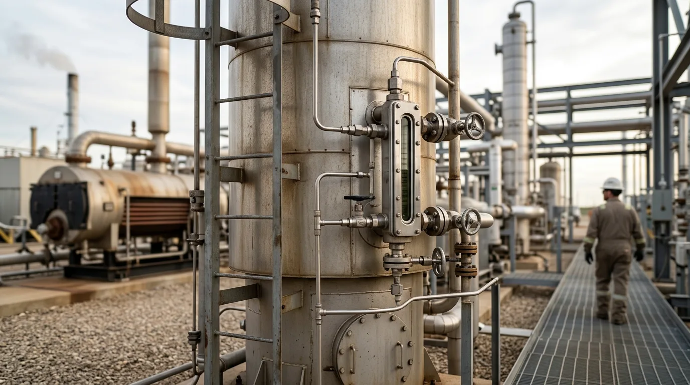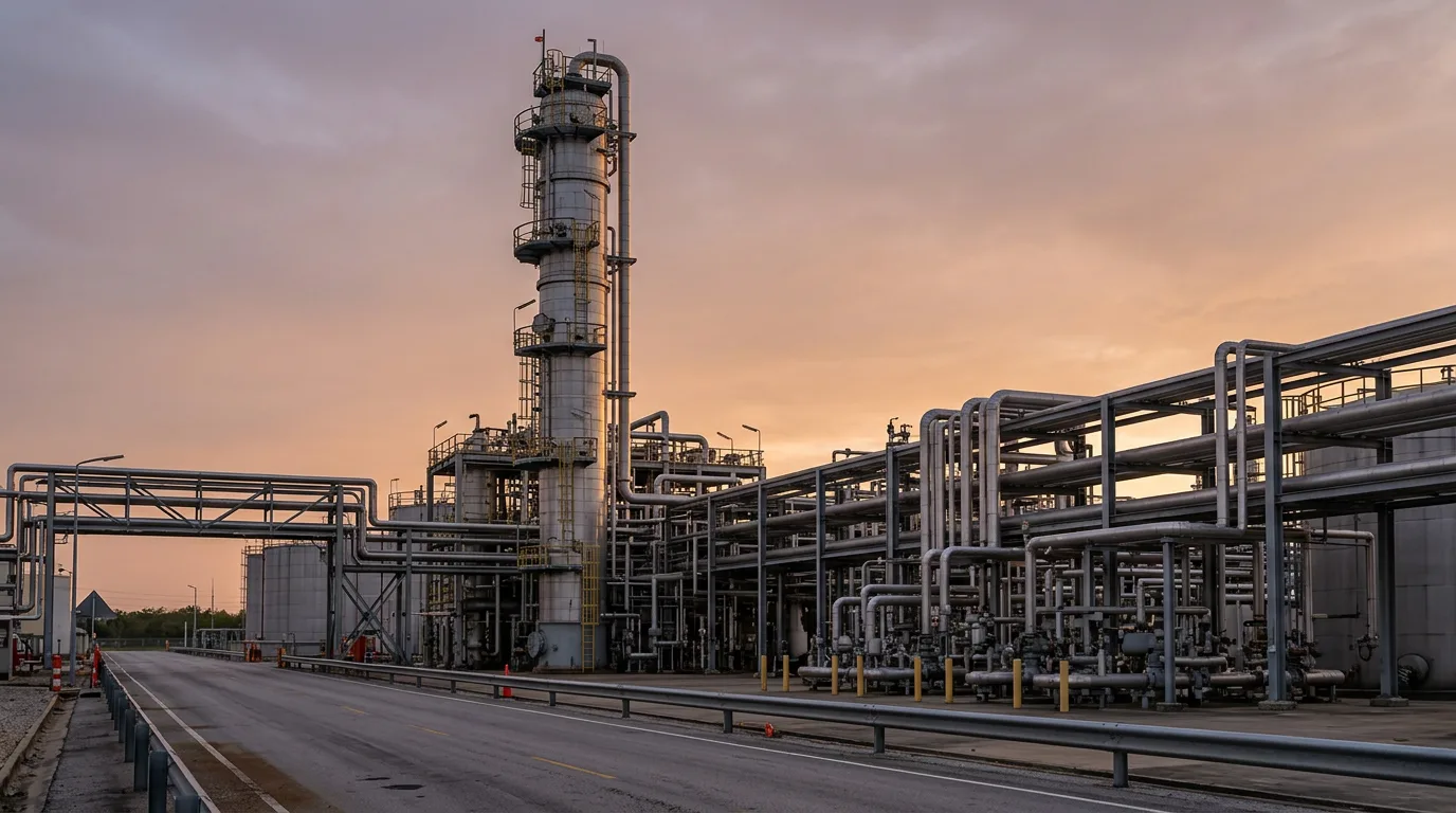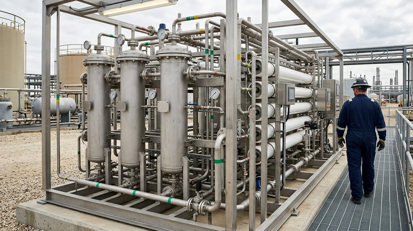
Why produced water is a hard cooling-water feed
A data-centre cooling loop needs a steady, low-fouling make-up stream. Permian produced water is the opposite. Oil loading swings, suspended solids are present, sulfide-producing bacteria live in it, production chemicals carry through, and dissolved solids are very high. Treat it as just another make-up source and the failures are predictable. Scale builds on heat-exchange surfaces. Biofilm blinds fill and exchangers. Corrosion products and oil carry-over feed the biology. Each of these cuts heat rejection, and it happens exactly where the data hall can least afford it.
The sources reviewed for this article agree on the root problem. Suspended solids, bacteria, corrosion by-products and fine particles drive fouling, scaling, corrosion and biofouling in treatment systems (). A review of hybrid produced water systems finds that performance is best when technologies are designed as integrated systems, with energy demand, fouling and scaling control, and pretreatment requirements as the dominant constraints (Systems-Level Optimization of Hybrid Produced Water Treatment Systems). This article follows that logic. Each step protects the next, and the design criteria work backwards from the cooling system.
Standards and requirements context
No single standard defines "cooling-quality produced water." The cooling system's metallurgy, the cycles of concentration you choose, the owner's water-quality specification and the discharge or disposal permit together set the bar. The following references are relevant:
ASHRAE 188covers risk management for Legionella in building water systems. Cooling towers fall within its scope, so the biocide programme and monitoring have to fit inside a water-management plan.ASTM D4189is the silt density index test for water. It is the usual acceptance test on filtered water ahead of membranes.EPA Method 1664measures n-hexane extractable material (oil and grease). It gives you a defined analytical basis for an oil-in-water guarantee, rather than a vague "free of oil" claim.
Beyond these, the controlling documents are the cooling-equipment vendor's make-up water limits, the state regulator's rules on produced water reuse outside the oilfield, and the site's management-of-change process. Cooper et al. (2022) in Oil and Gas Produced Water Reuse: Opportunities, Treatment Needs, and Challenges treat reuse outside the oilfield as a treatment-needs problem that depends on the end use. Pin down the end-use specification before you pick any equipment.
Technical body
Start with the salinity question
Oil removal, filtration and softening are pretreatment. On their own, they will not make Permian produced water fit for a cooling tower. The dissolved salinity is far beyond what a cooling system accepts as make-up. Softening strips out the scale-forming cations but leaves the salts behind, and those salts climb further every time the tower evaporates water.
So the design has two parts:
- A pretreatment train (oil, solids, hardness, biology) that protects the downstream equipment.
- A desalination step, membrane or thermal, that brings dissolved solids down to a level the cooling system can live with.
Use both to screen desalination options against your water chemistry.
Cooling blowdown is itself a waste stream. Settle its destination at the start, because that destination sets how hard you can push cycles of concentration.
Step 1: Oil removal
Oil comes first because it fouls every surface downstream. The usual sequence is gravity separation to pull out free oil, then a polishing stage for dispersed and emulsified oil. Polishing options include coagulation and flotation, media coalescers and, later, membranes. NETL describes an electrolytic coagulation and disinfection approach aimed at removing suspended solids, dispersed oil, H₂S, microorganisms and scale-forming cations from flowback and produced water (NETL, Non-Fouling, Low Cost Electrolytic Coagulation & Disinfection).
Design criteria:
- Size separators for the worst-case oil loading and upset conditions, not the average analysis.
- Write the oil-in-water guarantee at the outlet of the oil-removal step, with
EPA Method 1664as the measurement basis. - Allow surge capacity upstream. Slugs of oil and production chemicals are what wreck polishing media and membranes.
- Check demulsifier and other production-chemical carry-over. Surfactants can defeat coalescers and foul membranes.
Step 2: Solids filtration
Filtration takes out the residual solids and floc that come through from oil removal. Media filters followed by cartridge or ultrafiltration protection are the common arrangement ahead of membranes. Acceptance is usually set by turbidity and the ASTM D4189 silt density index at the filter outlet.
Design criteria:
- Provide backwash capacity and a destination for the backwash water. Oil-contaminated backwash must never go back to the front of the train untreated.
- Pick media that can handle residual oil, or put an oil-polishing stage upstream so the media never sees it.
- Trend differential pressure and filtrate quality against commissioning baselines. Drift tells you the upstream step is losing performance.
Step 3: Softening and scale control
Hardness and the other scale-forming cations are the main scaling risk. Chemical precipitation softening (lime or soda-ash based) and ion exchange are the standard tools. In very high-salinity water, ion exchange is hard to make work because the competing ion load is so high. Precipitation softening is usually the more workable choice, but it throws off sludge that has to be dewatered and disposed of.
Scale control in the cooling loop is a separate job from softening. Even with softened, desalinated make-up, concentration in the tower raises scaling potential. In practice:
- Set cycles of concentration by the least soluble scalant, not by TDS alone.
- Apply a threshold scale inhibitor and dispersant programme.
- Run pH control suited to the dominant scalants.
Silica and barium or strontium sulfate are the particular worries in oilfield waters. Some of these scales are very hard to remove once they have formed.
Step 4: Biofouling control
Produced water carries bacteria, sulfate-reducing populations included. The cooling loop then adds warm temperatures and nutrients, so biofilm risk runs high.
Design criteria:
- Strip nutrients and organics out upstream. Biocide demand climbs fast once oil and organics reach the loop.
- Rotate oxidising and non-oxidising biocides, and verify compatibility with residual production chemicals. Some organics consume oxidant and mask the true residual.
- Add side-stream filtration on the recirculating loop to catch the particulates that shelter biofilm.
- Tie monitoring and response to the
ASHRAE 188water-management plan.
Comparison of the train stages
| Stage | Main contaminant addressed | Typical risk if under-designed | Key design check |
|---|---|---|---|
| Oil removal | Free, dispersed and emulsified oil | Oil carry-over fouls filters and membranes | Outlet oil guarantee by EPA Method 1664; surge capacity |
| Filtration | Suspended solids, floc | Membrane fouling, high silt density index | ASTM D4189 at filter outlet; backwash handling |
| Softening | Scale-forming cations | Scaling in membranes and heat exchangers | Sludge handling; competing-ion load |
| Desalination | Dissolved salts | Make-up unusable at any practical cycles | Concentrate disposal route |
| Loop biocide and scale programme | Biology, residual scalants | Biofilm, under-deposit corrosion | Compatibility with residual organics |
Illustrative scenario
This is illustrative, not a real project. A facility engineer is evaluating a Permian produced water source for a data-centre cooling loop. The make-up has to balance evaporation and blowdown:
Make-up = Evaporation + Blowdown
and cycles of concentration, COC = Make-up ÷ Blowdown.
Rearranged, Blowdown = Evaporation ÷ (COC − 1). Raising cycles of concentration shrinks the blowdown volume, but it also drives every dissolved species toward its solubility limit. With this much dissolved salt and this many scale-forming ions in the water, the reasoning runs like this:
- Identify the limiting scalant in the concentrated water, using the full water analysis and the cooling-system vendor's limits.
- Choose the desalination step and softening duty so the limiting scalant stays under its limit at the target cycles.
- If the desalination duty needed makes the concentrate stream unmanageable, drop the cycles target or switch to a different make-up source.
- Confirm the concentrate and sludge have a permitted destination. The co-treatment idea in Ahmed et al. (2024) is worth a look here, since blowdown and produced water may be able to share a treatment path.
That does not mean produced water can't work. It means the disposal of concentrate and sludge, far more than the pretreatment, usually decides whether the project is viable.
Practical checklist
- Get a full, recent water analysis covering oil, solids, hardness, silica, sulfate, barium or strontium, bacteria and production chemicals. Repeat it across seasons and when well pads change.
- Get the cooling-system vendor's make-up and recirculating water limits in writing.
- Specify an analytical method for every guarantee, including
EPA Method 1664for oil andASTM D4189for silt density. - Define the concentrate, sludge and blowdown destinations and permits before selecting equipment.
- Confirm the make-up supply agreement covers volume and consistency.
- Include surge and equalisation storage ahead of oil removal.
- Test chemical compatibility between production chemicals, coagulants, scale inhibitors and biocides on actual water.
- Run a pilot on real produced water before committing to full-scale design, and include upset conditions.
- Fold the cooling-loop biocide programme into the
ASHRAE 188water-management plan.
Safety for maintenance on oily, sour water systems. Produced water vessels, separators and filters can hold hydrocarbons and H₂S. Before opening any of them:
- Isolate the equipment from all sources, with positive isolation.
- Depressurise it to a safe, designated vent or drain route.
- Verify zero energy by gauge and by physical checks.
- Apply lockout/tagout.
- Observe hazardous-area precautions, using only certified equipment.
- Test with a gas detector for hydrocarbons and H₂S, and keep monitoring during entry.
- Vent safely to a controlled location, never into an occupied space.
Conclusion
Getting Permian produced water to data-centre cooling quality is a train-design problem, and dissolved salts and concentrate disposal lead it, not oil removal alone. Oil removal, filtration and softening protect the desalination step and the cooling loop, and each needs a measurable acceptance criterion with a defined method. Next steps:
- Collect a representative water analysis and the cooling vendor's limits.
- Establish the concentrate and sludge route.
- Pilot the oil removal, filtration and softening sequence on real water.
- Only then size the desalination step and set the biocide and scale-inhibition programme.
If the disposal route can't be secured, reconsider the source before spending on equipment.