Anti-Surge Valve Sizing and Control Line Dynamics for Centrifugal Gas Compressors
Surge doesn't creep up on you. It's an abrupt reversal of flow, and it will take out impellers, seals and bearings in seconds. Every compressor station that handles gas needs a working anti-surge system, and the anti-surge valve (ASV) is the single most critical element in it. In the field, though, ASVs get misapplied all the time. Oversized valves produce instability and hunting. Undersized ones can't pull the machine back fast enough. A badly tuned control loop shows up late no matter how much capacity the valve has. Get the sizing and the control line dynamics right together and you protect the machine. Get one without the other and you don't.
Why Surge Happens and What the Control System Must Overcome
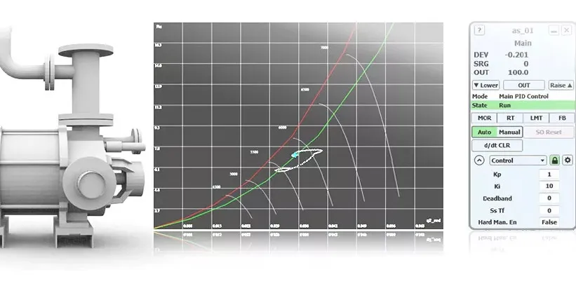
Surge is what happens when the compressor can no longer sustain flow against the system backpressure and the flow transiently reverses. The compressor map gives you a surge line — a locus of minimum-flow operating points across the speed range. The anti-surge control system has to detect the approach to that line and open the ASV to recycle gas back to the suction before the operating point crosses it.
Speed is the hard part. As documented in the Moore and Brun tutorial (Southwest Research Institute / Texas A&M Turbomachinery Laboratory), the compressor can enter surge within a fraction of a second of crossing the surge line. The control system must therefore act faster than the process dynamics allow the operating point to migrate. That places hard constraints on valve stroke time, actuator sizing, and signal latency — not just on valve flow capacity.
Standards and Requirements Context
Anti-surge systems sit at the intersection of process safety and rotating equipment protection. Relevant governing frameworks include:
- API 670 — covers machinery protection instrumentation, including the vibration, position, and process variable measurements that feed surge detection logic.
- API 672 and API 617 — establish performance and mechanical requirements for packaged and process centrifugal compressors, respectively, and include provisions for the control systems supplied with them.
- ISA-5.1 — governs instrumentation symbology used in surge control loop documentation.
- IEC 61511 — applies where the anti-surge function is classified as a Safety Instrumented Function (SIF), requiring a defined Safety Integrity Level and independent validation of the logic solver, sensors, and final elements.
Where a site risk assessment classifies surge prevention as safety-critical, the ASV and its actuator become part of a Safety Instrumented System and must be assessed under IEC 61511 accordingly. In many gas plant applications this is the case.
Valve Capacity Sizing
The Cv Requirement
The ASV must be capable of passing the full minimum recycle flow at the worst-case differential pressure — typically the maximum discharge pressure minus the minimum suction pressure. The standard control valve sizing equation for compressible flow applies:
For compressible gas flow at non-choked conditions (ISA-75.01 form): Q = N₇ · Cv · Fp · Y · √[(ΔP · P₁) / (γ · T₁ · Z)], where Y is the expansion factor accounting for pressure drop. For choked (critical) flow conditions, the expansion factor Y approaches a limiting value and the equation simplifies; the designer must use the choked-flow form from ISA-75.01 or equivalent.
Where:
- Q = volumetric flow rate (SCFH or Nm³/h depending on N₇ constant)
- Cv = valve flow coefficient
- Fp = piping geometry factor
- ΔP = differential pressure across valve (psia or bar)
- P₁ = upstream absolute pressure
- γ = specific heat ratio of gas
- T₁ = upstream absolute temperature
- Z = compressibility factor
You solve for the required Cv at the target Q, then pick a body size that delivers that Cv partway open — not at full stroke.
The 50% Open Rule
Industry practice, supported by the Gallois/Gas & Gear industry coverage, holds that a properly sized ASV should deliver the full minimum recycle flow requirement at approximately 50% open. That reserve capacity does two jobs. It lets the control loop modulate below full-open for steady-state recycle during startup or low-load operation. And when an emergency full-open signal is issued, the valve is already at useful flow capacity before it finishes its stroke — which cuts effective response time.
Oversizing Penalty
Push past the practical reserve and you create the opposite problem. A valve with excessive Cv spends its control range in the bottom fraction of its stroke, where hysteresis, seal friction, and nonlinear flow characteristics make precise modulation difficult. The result is hunting — the operating point oscillates around the surge control line rather than settling, inducing repeated near-surge excursions.
Control Line Dynamics
The Response Time Budget
The total system response time — from the moment the operating point begins moving toward surge to the moment adequate recycle flow is established — is the sum of several sequential delays:
- Measurement lag — transmitter response time for flow, pressure, and speed signals
- Signal transmission and scan time — controller cycle time and any fieldbus latency
- Controller computation and output — algorithm execution including any filtering
- Actuator response — time from output signal to valve beginning to move
- Valve stroke time — time to reach the required open position
No single element can be optimised in isolation.
Actuator Sizing for Stroke Speed
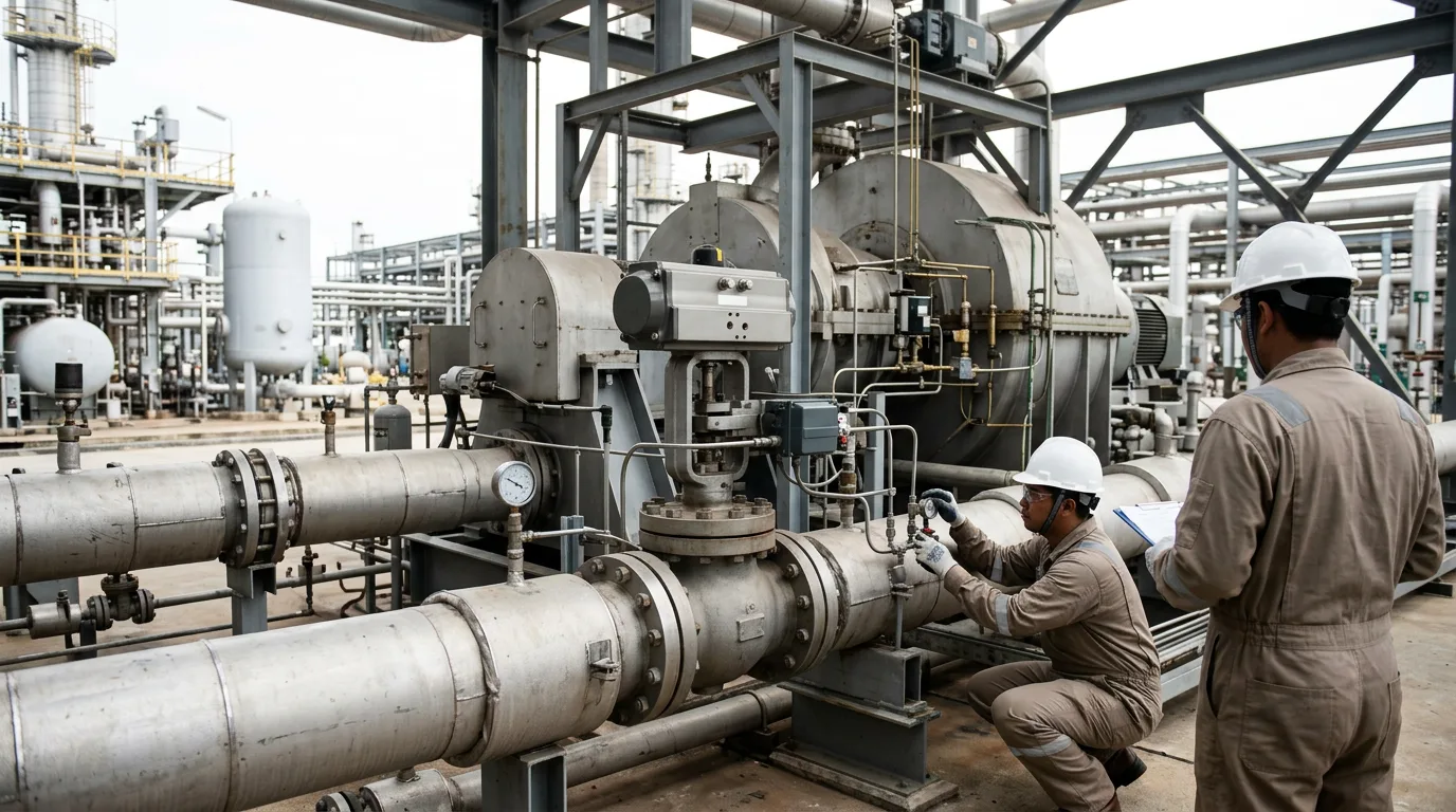
The actuator must be sized not only to overcome the valve's dynamic unbalance and packing friction at maximum differential pressure, but to do so at the required speed. Pneumatic actuators with volume boosters and quick-exhaust valves are the standard approach for high-speed ASV service. The supply volume, booster ratio, and tubing diameter between the positioner and actuator all affect achievable stroke speed.
The Surge Control Line Margin
The anti-surge controller does not act at the surge line itself — it acts at a surge control line set at a defined margin to the left of (or above) the surge line on the compressor map. That margin is what buys the control system time to respond before the operating point actually reaches surge.
Worked Example (Illustrative)
The following scenario is illustrative and constructed to demonstrate the sizing methodology. All values are hypothetical.
Given:
- Compressor design suction flow: Q_design = 10,000 Nm³/h
- Maximum discharge pressure: P₂_max = 80 bar(a)
- Minimum suction pressure: P₁_min = 20 bar(a)
- Therefore maximum ΔP across ASV: ΔP = 80 − 20 = 60 bar
- Gas specific gravity relative to air: SG = 0.65
- Suction temperature: T₁ = 313 K (40 °C)
- Compressibility Z ≈ 0.85 (read from equation of state at conditions)
- Required recycle flow basis: Q_recycle = 1.0 × Q_design = 10,000 Nm³/h
Step 1 — Check for choked flow: Critical pressure ratio x_T for a typical globe-style control valve ≈ 0.72 (valve manufacturer data). Actual pressure ratio x = ΔP/P₂ = 60/80 = 0.75, which exceeds x_T, confirming choked (critical) flow conditions. Sizing must use the choked flow form of the ISA equation.
For choked flow conditions, use the ISA-75.01 choked-flow equation: Q = N₉ · Cv · P₁ · √[x_T / (γ · T₁ · Z · M)], where x_T is the critical pressure ratio of the valve body (typically 0.72 for globe-style control valves), M is the gas molecular weight, and N₉ is the dimensional constant from ISA-75.01 corresponding to the desired flow units. Consult the full ISA-75.01 standard or validated valve sizing software to keep the dimensions straight.
Solving for Cv requires full gas molecular weight M and the applicable N₉ constant from ISA-75.01. Run the inputs above through a valve sizing software tool; the Cv it returns is your minimum required Cv at the recycle duty point.
Step 3 — Apply the 50% open rule: Select a valve body whose published Cv at 50% stroke equals or exceeds the calculated minimum Cv. The valve's full-open Cv will then be approximately double the recycle duty requirement, providing the emergency capacity margin.
Step 4 — Verify stroke time: With the selected actuator and booster configuration, confirm that the valve can stroke from closed to the 50% position within the time budget established by the surge dynamic analysis. If the compressor's characteristic surge approach time (from control line crossing to actual surge) is, for example, shorter than the total system response time calculated in Step 1 through 5 of the response budget above, the actuator must be upgraded or the control line margin increased.
Practical Checklist for Anti-Surge Valve Commissioning and Review
- [ ] Confirm ASV Cv is sized for 100% (minimum) of compressor design flow at maximum ΔP conditions
- [ ] Verify that full recycle flow is achievable at approximately 50% stroke, not full-open
- [ ] Check that the actuator supply pressure and booster sizing are documented and match the stroke speed test record
- [ ] Confirm positioner is configured for split-range or direct-acting mode consistent with fail-open requirement
- [ ] Review total response time budget: sum of transmitter, controller scan, output, and stroke time must be less than the surge approach time margin
- [ ] Confirm surge control line margin on the compressor map is consistent with the calculated total response time (Oh and Lee method or equivalent)
- [ ] Validate that the ASV does not hunt during steady-state recycle — if it does, check for oversizing or positioner gain mismatch
- [ ] Ensure the ASV is included in the site SIL assessment if the anti-surge function is classified as a SIF under IEC 61511
- [ ] Document the full-stroke test result (closed to open and return) at operating differential pressure, not just at no-load bench conditions
- [ ] Before any in-service work on the ASV: isolate suction and discharge, depressurise to verified zero energy, apply LOTO, confirm gas detection clearance, and vent safely to flare or atmosphere per site procedures
Conclusion
Anti-surge valve sizing cannot be treated as a simple flow calculation divorced from the control system's dynamic behaviour. The valve Cv, the actuator stroke speed, the transmitter response, and the controller scan time are all linked through the response time budget that determines whether the machine is protected or not. The 50% open sizing rule provides the necessary modulation range without sacrificing emergency capacity. Where the total response time is long relative to the compressor's surge approach dynamics, the surge control line margin must be widened — at the cost of usable operating range. The practical next step for any station review is to calculate the full response time budget from transmitter to established recycle flow, compare it against the compressor's dynamic behaviour from the performance map, and confirm that the margin is adequate before the next planned startup or capacity change.