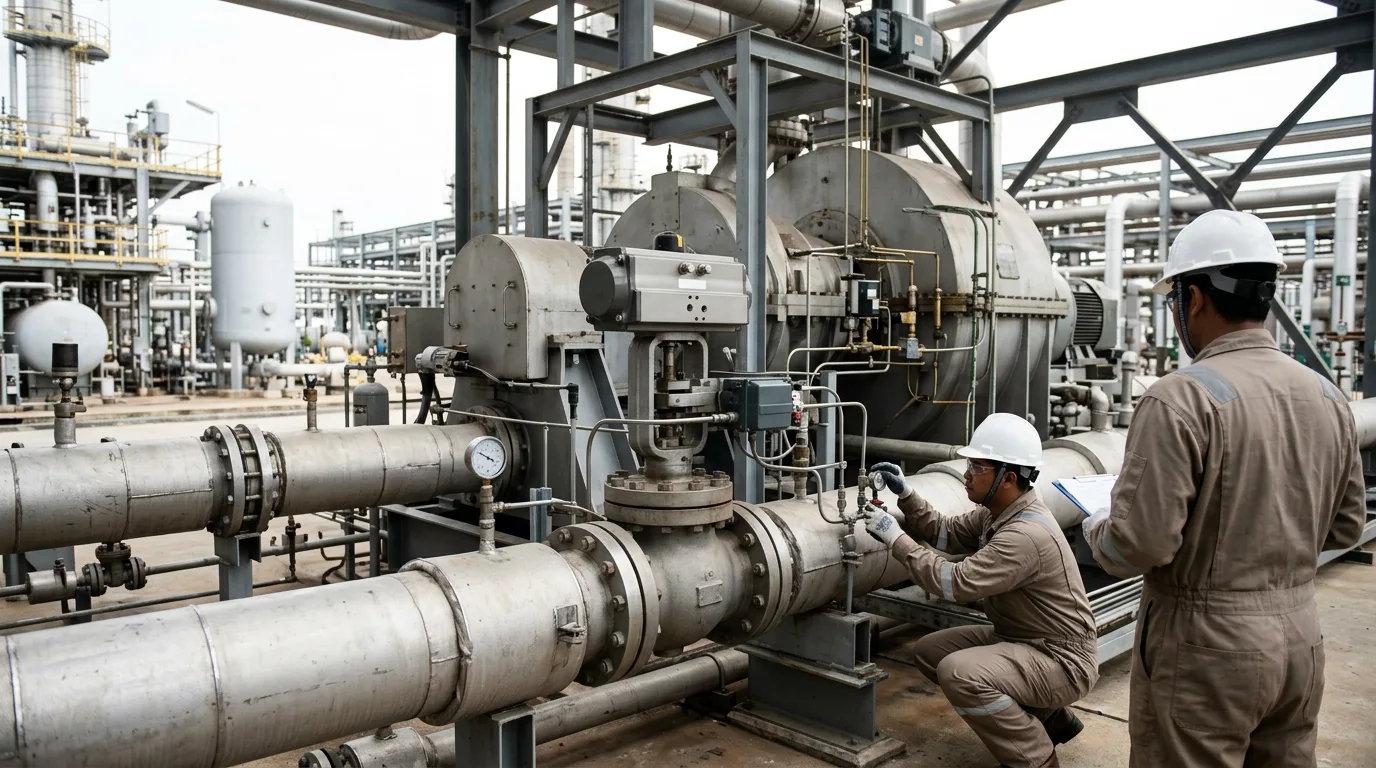
Antisurge valves are normally sized for the worst case, an emergency shutdown, and then asked to control the compressor during the far more common low-flow modes. A valve sized only for the trip case often can't throttle accurately near its closed position. The result is a limit-cycling recycle loop, wasted compression power, hot recycle gas, and nuisance trips when the controller overreacts. The opposite error is worse. A valve that is too small, too slow, or fed by an inaccurate surge line lets the machine reach surge on a trip. Surge damages seals, bearings and impellers, and it is the failure rotating-equipment engineers most want to avoid on a gas compression train.
This article walks through recycle valve sizing, response-time limits and surge-line mapping. It ends with a checklist for design review and commissioning.
Standards and requirements context
No standard prescribes a single antisurge valve size, so the engineer works from several documents:
- API 617 covers axial and centrifugal compressors and expander-compressors. It is the basis for the vendor's performance curves, surge point and rated conditions, which are the starting data for everything below.
- API 670 covers machinery protection systems. Vibration and position trips sit alongside the antisurge controller, and the two must be coordinated so a protective trip does not leave the recycle valve unable to protect the machine.
- IEC 61511 applies when the antisurge or trip-related valve action is allocated to a safety instrumented function in the process sector. Valve stroke time, partial-stroke testing and proof-test intervals then become verified design parameters, not just tuning preferences.
- IEC 60534-2-1 gives the flow-capacity sizing equations for control valves under installed conditions. The equations are standard, but compressor recycle service has unusual inlet and outlet conditions, so applying them takes judgement.
The compressor vendor's surge data, the control-system supplier's algorithm limits and the licensor's trip philosophy together define the performance target.
Understanding what the recycle valve must do
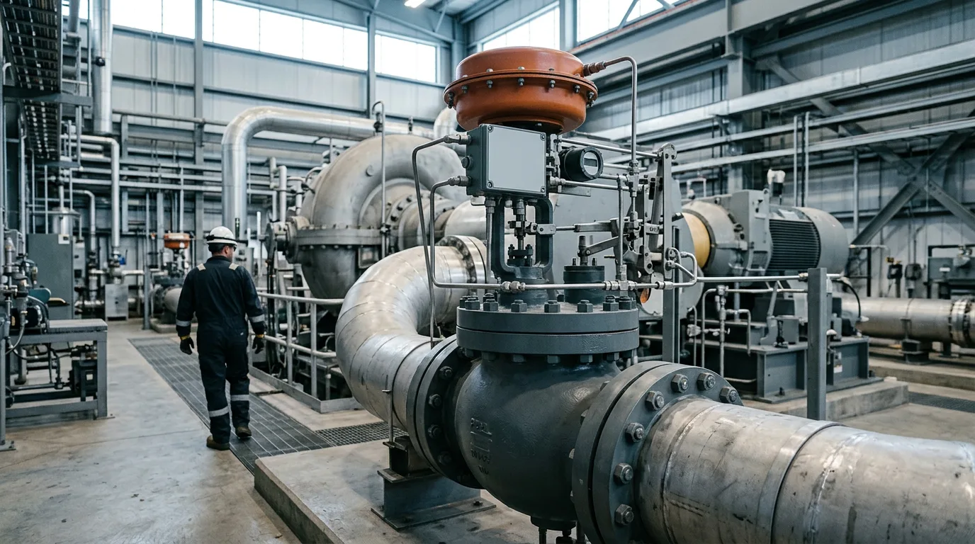
Surge control moves the operating point away from the surge limit by returning discharge gas to suction. Honeywell's May 2022 white paper on recycle valve sizing describes the recycle loop as a valve plus recycle pipework upstream and downstream, and every element affects performance. Valve capacity matters, but so do:
- the volume of gas trapped between discharge and the valve
- the pressure drop through the loop
- the temperature rise of recycled gas, if the loop is not cooled
- the dynamic response of actuator, positioner and tubing
The valve has two distinct duties, and they pull its design in different directions.
Emergency duty: shutdown and trip
On a trip, the compressor loses driver power while the discharge side is still at pressure. Gas flows backward through the machine unless the valve opens fast enough to unload the discharge side. This duty drives large capacity and fast opening.
Regulating duty: startup, turndown and process upsets
In normal operation the valve passes small flows, often at high pressure ratio, and it has to be positioned accurately. This duty drives characteristic, rangeability and positioner quality.
Sizing the recycle valve
Start from the surge flow, not the design flow
Sizing to surge flow gives you a starting point for the emergency case. It is not the final answer, for three reasons:
- The surge flow must be evaluated at the worst combination of suction pressure, temperature, gas molecular weight and speed. The surge flow in actual volumetric terms varies with all of these.
- It doesn't tell you what pressure drop the valve actually sees. Recycle service can have a low differential at high flow and a high one near closed, so choked and non-choked regimes may both occur.
- It doesn't check whether the oversized valve can still control the smallest required recycle flow.
A gross oversize pushes the working position toward the first few percent of travel. There, small actuator errors turn into large flow changes.
Check the low end explicitly
Establish the lowest recycle flow the control system will ever ask for. That may be a startup or a warm-recycle hold condition. Then confirm the selected trim can pass it at a controllable opening. If it can't, the options are:
- a valve with better rangeability
- a split-range arrangement with a small valve for regulation and a large one for trips
- a trim with a characteristic better matched to the control line
Each of these changes the sizing basis, so check them together.
Install the valve to preserve its capacity
Calculated capacity means little if the installation limits it. Check:
- recycle line size against valve outlet size, to avoid choking at the downstream pipe or reducer
- noise and vibration downstream of the valve at the highest differential
- gas cooling, so recycled gas doesn't raise suction temperature and drag the machine toward surge
- the volume between discharge check valve and recycle valve inlet
Response-time limits
Response time is the part of the design that is easiest to specify badly. The requirement comes from the compressor and piping, not from a generic stroke-time number.
Think of it this way. After a trip, the operating point moves toward surge at a rate set by the trapped gas volumes and the machine's rundown. The valve has to begin moving, pass enough flow, and relieve discharge pressure before the point reaches the surge limit. The total time includes:
- Controller scan and logic delay
- Solenoid or fast-acting dump delay
- Actuator and volume booster dynamics
- Valve travel to the required capacity point
- Gas dynamics through the recycle line
What this means in practice:
- Open the valve quickly on a trip, but close it more slowly under regulation, to avoid pressure disturbance and re-entry into surge.
- Specify actuator air supply, tubing, boosters and quick-exhaust devices as part of the response-time requirement. Undersized tubing can end up dominating the dead time.
- Verify the stroke on site, with the real air supply and measured positioner feedback. Don't rely on the factory numbers alone.
Surge-line mapping
From vendor curves to a control line
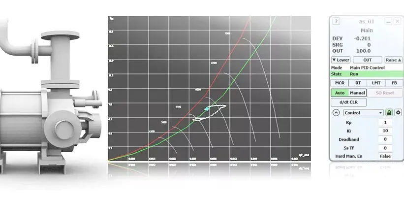
The vendor curve gives a surge limit at specified conditions. The controller needs a line in coordinates that stay valid when suction conditions change, typically reduced or invariant variables. The control line is then offset from the surge limit by a safety margin. That margin is a design decision, driven by measurement accuracy, process dynamics, and how well the line has been verified.
Key points:
- A larger margin is safer but leaves less usable operating range and means more recycle.
- A smaller margin demands better flow measurement, better surge-line verification and a faster valve.
- A backup or trip line, set closer to the surge limit, supports a rapid open command if the operating point crosses it.
Field verification
The vendor curve is a prediction. The installed surge point can differ because of inlet piping, gas properties, wear, and instrument calibration. A controlled field surge test is the standard way to confirm the line, but it carries risk. Approach it with:
- a written procedure agreed by operations, the vendor and control engineers
- instrumentation for rapid sampling of flow, pressure, temperature and vibration
- an approach in small steps, with a predefined abort action
- conservative handling of the first surge indication
After the test, record the actual surge points against the vendor curve, then update the controller's surge line and margin to match.
Tuning the control loop
The antisurge controller combines a primary PI action with a fast open-loop response when the operating point crosses the control line. Tuning has to follow valve sizing, because gain depends on valve characteristic and operating position.
- Confirm instruments first: transmitter ranges, damping, scan rate and flow-element accuracy.
- Characterize the valve with stroke and step tests at several positions, noting dead time, hysteresis and travel speed.
- Set proportional and integral action for stable regulation at the typical recycle position, then check at the low and high ends.
- Configure the fast open response so it overcomes dead time without causing repeated cycling.
- Test a trip scenario under conditions that mimic site data.
Cycling around the control line usually points to one of three things: a valve that is oversized or has high gain near closed, a margin too close to the surge limit for the measurement noise, or a controller gain that doesn't match the valve characteristic.
Illustrative scenario
This scenario is illustrative and is not drawn from a listed source. A gas compression train has a recycle valve sized by the compressor vendor's rule of passing 1.8 to 2.2 times the maximum surge flow. If the maximum surge flow is expressed as 1.0 normalized flow unit, the valve must pass 1.8 to 2.2 normalized flow units. During commissioning, the plant finds that the valve cycles at normal low-load operation, even though trip testing is satisfactory.
Work through the checks in order:
- Plot valve position during the cycling. If it sits near closed, the valve is working in the most sensitive part of its stroke.
- Check the characteristic. An equal-percentage or quick-opening trim has particularly low or high gain in that range, and the oscillation will show it.
- Add controller characterization, or reduce gain at low openings.
- If the valve still can't hold the required low flow, evaluate a smaller regulating valve in split-range with the large trip valve.
- Repeat the trip test to confirm the emergency response hasn't been compromised.
The lesson: a successful trip test doesn't prove regulating performance, and the reverse holds too.
Safety during valve and instrument work
Any work that opens the recycle valve, actuator connections, or the process side must follow the site permit system:
- isolate the recycle line, with double block and bleed where available
- depressurize through the approved route, venting safely to flare or a designated system
- verify zero energy with gauges and bleed points before breaking containment
- apply LOTO to the valve, actuator air supply, and driver
- treat the area as hazardous, using certified tools and test equipment
- use portable and fixed gas detection throughout
Stored actuator energy is a hazard in its own right. Spring and air energy must be released and verified before disassembly.
Design review and commissioning checklist
- Surge flow evaluated at the worst combination of suction pressure, temperature, gas composition and speed.
- Valve capacity calculated for emergency conditions, with the sizing basis documented, including the 1.8 to 2.2 manufacturer guideline where used.
- Lowest required recycle flow checked against controllable valve opening.
- Valve characteristic selected deliberately, with controller compensation if equal-percentage or quick-opening.
- Discharge volume, recycle line size, and gas cooling considered in the response analysis.
- Dynamic simulation or equivalent analysis used to set the response-time requirement.
- Air supply, tubing, boosters and exhaust sized as part of the stroke-time requirement.
- Instrument ranges, scan rates and filtering confirmed before tuning.
- Surge line defined in invariant coordinates, with margin and backup line documented.
- Field surge test procedure approved, with abort criteria and instrumentation ready.
- Trip, regulation and startup scenarios each tested after tuning.
- Valve, positioner and solenoid test results recorded as the baseline for future maintenance.
- Safety function requirements aligned with IEC 61511 where the valve is part of an SIF.
Conclusion
Recycle valve sizing is a compromise between emergency capacity and regulating control. Start with the manufacturer's surge-flow guideline, then verify low-flow controllability, characteristic, installation effects and response time against the real train. Treat the surge line as a measured quantity, not just a vendor prediction, and tune the controller only after the valve behaviour is characterized.
For the next step, gather the compressor maps, valve datasheets, piping volumes and instrument specifications for your train. Then run the checklist above in a joint review with rotating equipment, controls and operations. Where the answers are unclear, commission a dynamic study before the next turnaround.