The problem: a driver choice that locks in plant output for decades
In an LNG liquefaction plant, the refrigeration compressor driver sets the throughput ceiling. It also decides how sensitive the plant is to ambient conditions, what its maintenance pattern looks like and how carbon-intensive it becomes. Pick a driver that doesn't match the refrigeration duty, the site climate or the power-island philosophy, and you'll lose production on hot days. Restarts after trips get harder. The outage burden turns up in operations, not in the business case. Once the compressor strings are installed, none of this is cheap to fix.
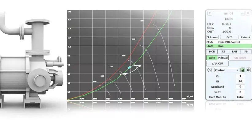
The KBC Advanced Technologies paper on suitable LNG driver selection makes the central point. LNG plants are energy- and cost-intensive, so the driver has to be evaluated as an integrated model of turbine, compressor and process, including off-design performance and emissions. Comparing ISO-rated nameplate numbers won't do it. This article walks through the selection criteria in the order a process engineer would actually work them.
Standards and requirements context
Driver selection sits inside a set of codes, and a handful of them shape most decisions:
API 616covers gas turbines for the petroleum, chemical and gas industry services. It's the baseline specification for turbine mechanical design, auxiliaries and testing.API 617covers axial and centrifugal compressors and expander-compressors. The compressor and driver train have to be specified together, and the compressor's speed range and torque demand feed straight back into turbine selection.API 670covers machinery protection systems. Vibration, axial position and temperature monitoring on multi-casing LNG strings should be defined at the selection stage. Leave it to detailed design and it tends to get squeezed.NFPA 59Acovers the production, storage and handling of LNG.EN 1473covers the design of onshore LNG installations. Both affect turbine and compressor layout through hazardous-area classification, spacing and gas detection.IEC 61511governs functional safety for the process industry. Turbine trip logic, fuel gas isolation and refrigerant compressor protection typically sit within the safety instrumented system lifecycle.
Project specifications and licensor requirements usually add to this list. Treat it as the minimum.
Technology options
Gas turbines in LNG show up in two roles. They act as mechanical drivers coupled directly to refrigerant compressors, or as power generation for the plant's electrical loads, including electric-motor-driven trains. The AIChE papers on power generation selection (2010) and on net present value in gas turbine generator selection (2015) cover the second role. Meher-Homji's Gas Turbines and Turbocompressors for LNG Service (2007) covers the first.
Heavy-duty industrial gas turbines
These are the established workhorses of large liquefaction trains. Single-shaft or two-shaft, they're built for continuous base-load duty with robust casings and long inspection intervals. For LNG, their main limits are:
- Lower simple-cycle efficiency than aeroderivatives. That means more fuel gas burned per unit of refrigeration shaft power.
- A single-shaft arrangement ties compressor speed to turbine speed. You'll need a large starter or helper motor, and compressor settle-out pressure at start needs careful handling.
- Output is strongly tied to inlet air temperature, so hot-site performance needs explicit evaluation.
Aeroderivative gas turbines
Aeroderivatives are lighter. They run a gas generator feeding a free power turbine. You get higher thermal efficiency and a modular maintenance philosophy. The gas generator can be swapped out and overhauled off-site, which shortens the outage on the string. The trade-offs:
- Smaller unit size. A given refrigeration duty may need more strings or a different compressor split.
- More sensitivity to inlet air quality, which matters at coastal and dusty sites.
- Output that falls off with ambient temperature, same as heavy-duty machines.
Two-shaft versus single-shaft architecture
A two-shaft machine decouples the power turbine from the gas generator. That gives a wide speed range for the driven compressor, easier starting at lower starter torque and good part-load behaviour on refrigeration duty. The arrangement is now a standard option in LNG service.
Electric motor drive with gas turbine generation
Electrifying the compressor strings moves the combustion to a central power island. The drivers become motors, fixed-speed or variable-speed, and the turbines become generators. That changes the selection problem:
- Power-island turbines can be optimised for generation efficiency, potentially with waste heat recovery.
- The plant gains grid-connection and renewable-power options.
- The electrical system, including harmonics, ride-through and black-start, becomes a primary design concern.
The Decarbonization of Gas Turbine Driven LNG Liquefaction Plants – Design Options and Challenges paper (2024) by Taher and Meher-Homji addresses these design options and their challenges for gas-turbine-driven plants. Read it before you commit to a driver philosophy on a new project.
Comparison of driver options
| Criterion | Heavy-duty single-shaft | Heavy-duty two-shaft | Aeroderivative | Electric motor with GT power island |
|---|---|---|---|---|
| Unit size availability | Largest frame sizes | Large | Smaller units, more strings | Flexible, set by power island |
| Fuel efficiency (relative) | Lower | Lower to moderate | Higher | Depends on generation cycle |
| Speed flexibility | Limited, tied to turbine | Wide | Wide | Depends on drive type |
| Starting duty | Large starter or helper needed | Moderate | Moderate | Electrical start system |
| Maintenance approach | In-situ inspection, long intervals | In-situ inspection | Module exchange | Split between motors and turbines |
| Ambient sensitivity | High | High | High | Moves to power island |
| Decarbonization route | Fuel and capture options | Fuel and capture options | Fuel and capture options | Grid or renewable power |
All entries are qualitative. Vendor data at your site conditions replaces them.
Selection criteria in detail
Refrigeration duty and process fit
The liquefaction process (a propane-precooled mixed refrigerant cycle, for example) sets the compressor strings and the shaft power each one needs. The Gas Processing News article on process selection and design innovations (2017) states that LNG technology selection involves parameters such as compressors, turbines and heat exchangers together with the process. In practice the sequence runs one way. Fix the process and compressor train first, then size the driver to the compressor's power and speed envelope. Don't start with a favourite turbine and bend the process around it.
Ambient temperature and site conditions
Turbine output drops as inlet temperature rises, and LNG plants often sit in hot, humid coastal locations. The refrigeration duty also gets harder when the cooling medium is warm. The two effects stack. A driver sized at ISO conditions will under-deliver on the hottest days. Evaluate the full ambient envelope, and treat inlet air cooling and filtration as part of the driver package.
Off-design performance and emissions
The KBC paper's approach uses an integrated model that combines turbine, compressor and process behaviour, so performance and emissions can be checked across off-design cases. Do this during selection, not after. Cases to include:
- Hot-day, turndown and cold-day operation.
- Degraded compressor and turbine performance late in the maintenance cycle.
- Reduced-rate operation when a train is down.
Starting, helper motors and power balance
A helper motor on the string improves start capability. It can also add shaft power when ambient conditions limit the turbine. That pulls the electrical system into the mechanical-drive decision. Check the plant power balance, the starting voltage dip and the black-start sequence alongside the driver selection, not after it.
Availability, maintenance and outage strategy
Maintenance planning and parallel execution matter as much as machine choice. When comparing options, ask:
- Is the outage in-situ or by module exchange?
- Does the site have space and lifting capability for the chosen turbine?
- Is a spare gas generator or power turbine economic given the fleet?
Economics: lifecycle, not capital cost
The AIChE net present value case study (2015) applies NPV to generator selection. The method matters more than any single result. Compare options on lifecycle cost, including fuel gas consumption, maintenance, lost production exposure and emissions cost. Installed cost alone tells you very little. Fuel gas burned in the driver is gas that never gets sold as LNG, so efficiency gaps are worth real money over the plant's life.
Decarbonization readiness
Design for the carbon policy the plant will face over its life, not just today's. Options include waste heat recovery, electrification, alternative fuels and carbon capture. Each one has layout, utility and control-system consequences. Those are cheap to provide for at the design stage and expensive to retrofit.
Illustrative scenario
This scenario is illustrative and does not describe a real project.
A project team is choosing between heavy-duty two-shaft turbines and aeroderivative turbines for the refrigerant compressors of a coastal, hot-climate liquefaction plant. Initial screening favours the aeroderivative on fuel efficiency. The team then builds an integrated model along the lines of the KBC paper.
- They run the model across the full ambient envelope, not just ISO conditions. Both turbine types lose output on hot days, and the compressor strings become the bottleneck.
- They add degraded-condition cases. The aeroderivative's air filtration and coastal salt exposure turn into a significant design item, and it needs a high-grade inlet system.
- They review maintenance. Module exchange shortens each aeroderivative outage, but the site needs lifting access and a spare gas generator strategy.
- They compare lifecycle cost using an NPV approach like the 2015 AIChE study. Fuel savings from the aeroderivative get weighed against the extra strings and the inlet system.
- They check the decarbonization path. Electrification would shift the problem to a power island, so the layout reserves space for either option.
The outcome depends on the weighting. Without the integrated model, the team would have decided on nameplate efficiency alone.
Decision checklist
- Define the process and compressor train first, then size the driver to its power and speed envelope.
- Obtain vendor performance across the full ambient range, including degraded-condition cases.
- Evaluate single-shaft versus two-shaft against starting duty, speed range and part-load operation.
- Decide helper-motor use and check the plant electrical system and black-start sequence.
- Specify inlet air filtration and cooling for the actual site air quality.
- Compare in-situ maintenance with module exchange against site lifting access and spares strategy.
- Build the lifecycle cost on an NPV basis, with fuel gas consumption as an explicit line.
- Confirm machinery protection scope under
API 670and the trip logic under theIEC 61511lifecycle. - Check hazardous-area classification and spacing against
NFPA 59AandEN 1473. - Reserve layout and utility provisions for the chosen decarbonization route.
- Record the assumptions behind the selection so they can be tested when site data arrives.
Conclusion and next steps
Driver selection for an LNG plant is a system decision. The best machine on paper can turn out wrong once ambient derating, starting duty, maintenance access and decarbonization enter the picture. Start with the process and compressor train, build an integrated off-design model, and compare options on lifecycle cost.
Next steps: request vendor performance data across your site's full ambient range, build or commission the integrated model, and read the Meher-Homji 2007 paper and the 2024 decarbonization paper before finalising the driver philosophy.