The operational problem
A platform fed by a single long export cable has no local power to fall back on. When the cable, converter or control system trips, compression, water injection and export all stop. Restart depends on how quickly the converter, the DC link and the grid connection can be brought back in a coordinated way. The supply contract and cable repair logistics decide whether that takes hours or weeks. Power-from-shore removes local turbine maintenance and emissions, but it concentrates the risk in a small number of large, hard-to-replace assets: the cable, the two converter stations and the protection scheme between them.
HVDC is the natural option when distance makes HVAC cable charging current and reactive compensation impractical. It brings its own problems: topside footprint, DC fault behaviour, harmonic interaction with large motor drives, and cable lifetime. This article covers those problems from the viewpoint of the people who specify, operate and maintain these systems.
Standards and requirements context
No single standard covers an offshore HVDC platform supply. In practice you pull the requirements together from several sources:
IEC 61892(all parts) covers electrical installations on mobile and fixed offshore units.IEC 61892-1sets the general requirements.IEC 60079-14covers the design, selection and erection of electrical installations in explosive atmospheres. It applies to everything installed in classified areas, including converter-related auxiliaries and cable entries.IEC 62477-1covers safety requirements for power electronic converter systems and equipment. It is a useful basis for converter and drive safety reviews.IEC 61000-2-4gives compatibility levels for low-frequency conducted disturbances in industrial plants.IEEE 519gives recommended practice for harmonic control in power systems. Both are used to define power quality at the platform busbar.IEC 61511applies where the electrical supply scheme, load shedding or shutdown logic forms part of a safety instrumented function.
HVDC-specific items such as converter station performance, DC cable type testing and DC protection philosophy are normally set in the project specification and agreed with the supplier. Don't assume a generic standard fills those gaps.
Technical body
Why HVDC for remote platforms
Platform electrification and offshore wind share the same transmission options, but they pull in different directions. A wind connection exports power. A platform is an isolated load with large motors and strict availability needs.
The engineering driver is cable physics. An AC subsea cable draws charging current that grows with length, and that current eats into the cable's capacity, so reactive compensation becomes necessary at long distances. A DC cable carries no charging current in steady state, and the converters take over reactive power control. PSC Consulting (2019) describes HVDC as an established way of connecting remote offshore resources such as wind farms and supplying power to offshore installations.
| Aspect | HVAC supply | HVDC supply (VSC-based) |
|---|---|---|
| Cable charging current | Increases with length and limits reach | Absent in steady state |
| Reactive compensation | Often needed along or at ends of the route | Provided by converter control |
| Topside equipment | Transformers, reactors, switchgear | Converter station, DC filters, cooling, converter transformer |
| Fault behaviour | Well-understood, breaker-cleared | Depends on converter topology and DC protection design |
| Grid decoupling | None; AC faults propagate | Converters can decouple platform and shore systems |
| Maturity in platform use | Wide | Fewer installations; strong dependence on supplier |
Topside footprint, weight and cooling
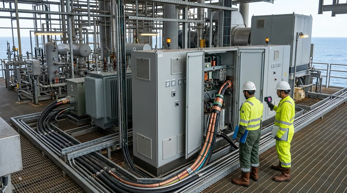
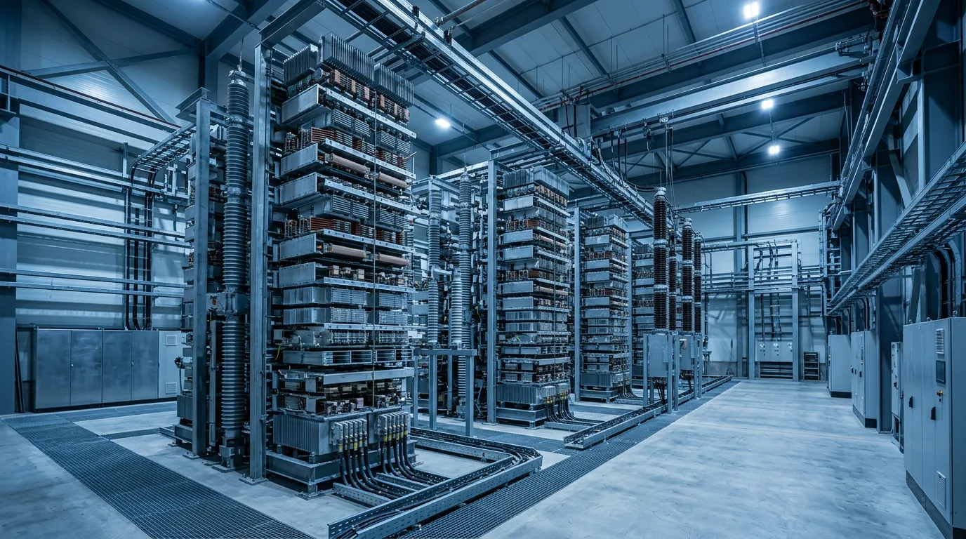
Converter stations are the main topside headache. They need valve halls, cooling, filters and auxiliary supplies, and all of that takes up space and weight on a structure that was often designed decades earlier. The Troll A paper (IET ACDC, 2006) is the primary reference here. It describes the construction challenges of bringing HVDC power to one of the largest oil and gas platforms in the world. Its main lesson applies to every retrofit: installation sequence, interface management and offshore commissioning are as demanding as the electrical design.
Practical consequences for retrofit projects:
- Confirm structural capacity and laydown routes early. The converter modules may be among the heaviest lifts ever made on the platform.
- Treat the cooling system as a critical subsystem. Lose converter cooling and you lose power transmission.
- Verify the hazardous-area classification of the proposed location. Valve halls are normally in safe areas with pressurisation or HVAC, but air intakes, cable routes and ventilation inlets must be checked against
IEC 60079-14.
Interaction with large motor drives
Platform loads are dominated by variable-speed drives on compressors and pumps. At the platform end, the converter feeds a weak, isolated network with no stiff grid to soak up disturbances. The key issues are:
- Harmonic distortion on the platform busbar, from drives, filters and the converter itself. Assess against
IEEE 519andIEC 61000-2-4limits agreed in the specification. - Motor start and drive trip transients. A large drive trip is a sudden load rejection, and converter control has to ride through it without tripping the link.
- Resonance between filters, cable capacitance and drive input stages. This needs a system study across the full frequency range, not just the fundamental.
- Control interaction. When converter and drive controls come from different suppliers, an integrated dynamic model is the only reliable way to find negative-damping interactions before commissioning.
DC faults and protection
A DC cable fault is the defining design case. Depending on converter topology, the converter may keep feeding the fault through its freewheeling paths until the AC side is tripped. The result is a full loss of platform supply. Questions to put to the supplier:
- Which converter topology is used, and how does it limit or block DC fault current?
- Is the cable pole-to-ground, pole-to-pole or bipolar-with-return, and what happens to the healthy pole after a single-pole fault?
- What is the restart sequence after a transient fault, and is automatic reclosing permitted?
- How is the platform protected from shore-side converter trips, and how does the load-shedding scheme respond?
Any link between transmission protection and process shutdown logic should be reviewed under IEC 61511 if it forms part of a safety function.
Cable systems
The cable is the longest-lead item and the hardest to repair. NKT describes its offshore DC cables, including dynamic cables built for high fatigue endurance under constant movement. That matters for floating platforms, where the riser section sees continuous cycling. Static export sections face a different set of threats: burial, crossings and third-party damage.
Key points for owners:
- Terminations and joints are typically the weak points, so require full type-test and installation-qualification evidence for them.
- Plan the repair strategy before award. That means spare cable length, jointing capability and vessel access, because repair time often dominates outage time.
- Monitor the cable after installation. Distributed temperature sensing and fault location capability help with burial depth issues and early damage detection.
That also shows operators now buy cable and electrification as one integrated package, with interface responsibility sitting with the supplier.
Alternative DC architectures
For subsea or distributed loads, the modular stacked DC (MSDC) concept (IEEE Transactions on Industry Applications, 2014) proposes series-connected DC modules for long-distance transmission and distribution. It avoids large subsea AC transformers and supports distribution to subsea loads. The architecture and power conversion review by Ray and Rajashekara in Energies (2023) compares options for electrifying offshore production, including how DC distribution and power electronics might be arranged. These approaches are still maturing. Treat them as options to evaluate, not drop-in substitutes for the proven topside converter.
Illustrative example: why transmission voltage matters
This is a simplified, illustrative calculation, not a project sizing. It shows why voltage level drives both loss and cable current.
For a DC link delivering power P through a conductor of resistance R at voltage V:
- Current: I = P / V
- Conductor loss: P_loss = I² × R = P² × R / V²
Now keep P and R fixed and double the voltage, V₂ = 2 × V₁:
- P_loss,2 = P² × R / (2V₁)² = P² × R / (4 × V₁²) = P_loss,1 / 4
Result: for the same delivered power and the same conductor, doubling the voltage cuts conductor loss to a quarter and halves the current. This ignores converter losses, insulation limits, return-path effects and load-dependent voltage drop, all of which a real design has to include. In practice the voltage is chosen from the cable's insulation capability, the converter technology available, and the cost of the topside equipment.
Decision checklist
Specification and design:
- Define the availability requirement for the platform supply, and decide whether partial transmission capability after a single-pole fault is required.
- Obtain an integrated dynamic study covering converter, filters, cable and the largest drives, including load rejection and restart.
- Confirm the harmonic limits at the platform busbar and who is responsible for compliance.
- Decide the fallback philosophy: retained local generation, a second cable, or a controlled shutdown.
- Review topside structure, weight, cooling and air intake locations against area classification.
Procurement:
- Require type-test and installation-qualification evidence for DC cable terminations and joints.
- Clarify interface responsibility between cable, converter and platform control suppliers.
- Agree a spares strategy for cable length, converter modules and cooling components, and confirm repair vessel access.
- Require a defined software and control version management process, because converter control is part of the protection.
Operations and maintenance:
- Treat stored energy in DC capacitors and cables as live until verified otherwise. Apply isolation, discharge, verification of zero energy and lock-out/tag-out before any work, following the supplier's procedure.
- For work in or near classified areas, apply hot work and hazardous-area permit controls, use gas detection, and keep any venting routed to a safe location.
- Rehearse black start and restart after a transient fault with operations staff before first power.
- Trend converter cooling performance, filter condition and cable monitoring data against the commissioning baseline, and investigate sustained drift.
Conclusion
HVDC supply to remote platforms trades local generation for dependence on a few large assets. Most of the engineering risk sits at the interfaces: converter to weak platform network, protection to process shutdown, and cable to repair logistics. The Troll A experience (IET, 2006) shows that offshore construction and commissioning are as demanding as the design itself.
As next steps, commission an integrated dynamic study early, write the DC fault and restart philosophy into the specification, and settle the cable repair strategy before award. Then check the proposed arrangement against the checklist above, and use the IEC 61892 and IEC 60079-14 requirements as the basis for the platform-side installation review.