Variable Frequency Drive Harmonics on Islanded Offshore Power Systems: Causes and Mitigation
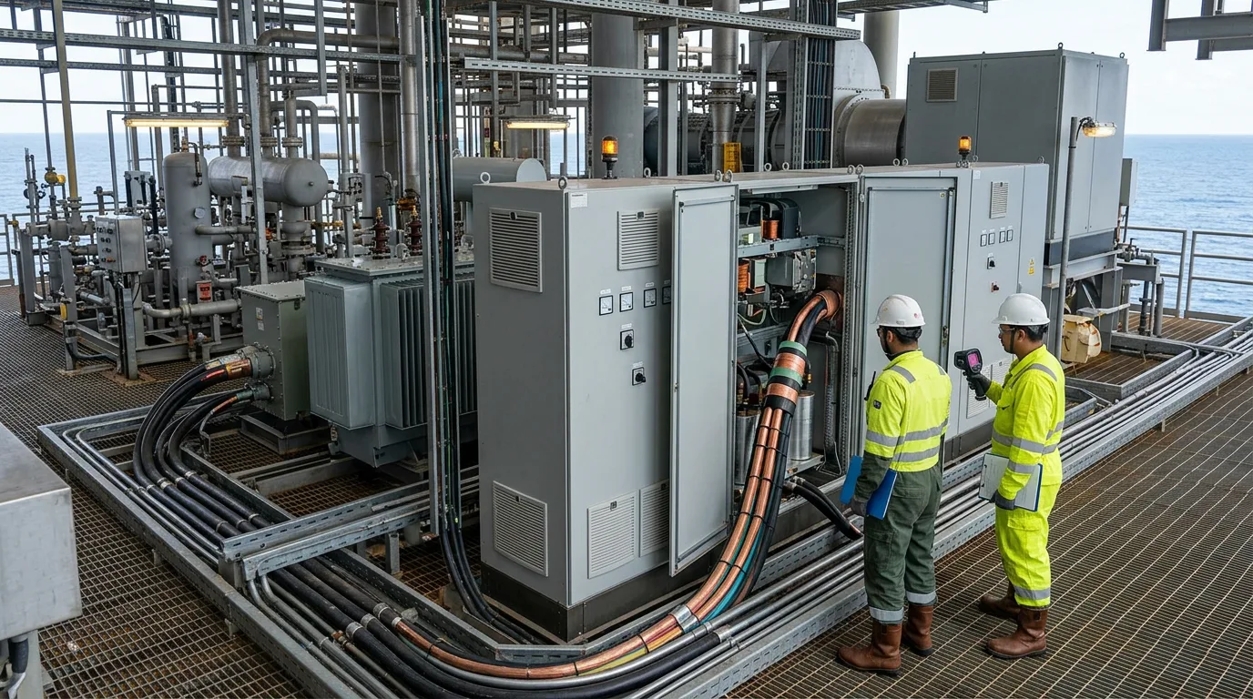
Offshore platforms and floating production units are islands. A handful of gas turbine or diesel generators feed a finite bus, and there is no grid connection behind them to soak up disturbances. On most modern facilities, variable frequency drives (VFDs) carry a large share of that load — compressors, pumps, fans. When they do, harmonic currents circulate through the closed bus and distort the voltage waveform for every other consumer on the same switchboard. The bill shows up as hot transformer and motor windings, nuisance tripping of protection relays, metering errors, and insulation ageing faster than it should. On a utility grid the stiff source dilutes all of this. On an islanded platform the generator impedance is the only buffer, and it is rarely adequate.
Why Islanded Systems Are Uniquely Vulnerable
A VFD's front-end diode rectifier does not draw a sinusoid. It draws current in pulses. Those pulses are mathematically the fundamental plus a series of integer multiples — harmonics. In a six-pulse rectifier the fifth and seventh dominate; higher orders are smaller but far from negligible. Characteristic harmonic orders for a pulse-number p drive follow:
h = kp ± 1, where k = 1, 2, 3 …
So a six-pulse drive (p = 6) produces h = 5, 7, 11, 13, 17, 19 … and so on.
On a utility grid, the short-circuit ratio at the point of common coupling is high — source impedance is low next to the load — so harmonic currents cause only modest voltage distortion. Offshore, the ratio is low. Generator subtransient reactance dominates, and the same harmonic current buys proportionally more voltage distortion.
Autonomous or islanded microgrids carry an extra complication: there is no external voltage reference to absorb reactive harmonic power. Whatever harmonic current the nonlinear loads demand, the grid-forming inverters or synchronous generators have to supply or sink. If the control bandwidth of those sources is insufficient, total harmonic distortion (THD) of the bus voltage climbs above the threshold at which sensitive instrumentation and protection systems begin to malfunction (Autonomous Control of Inverter-Interfaced Distributed Generation Units for Harmonic Current Filtering and Resonance Damping in an Islanded Microgrid).
Applicable Standards
IEEE 519 is the primary harmonic quality benchmark for offshore power systems — it caps current THD at the point of common coupling and voltage THD at the bus. For equipment on European-flagged or North Sea installations, IEC 61000-2-4 defines compatibility levels for industrial and power-plant environments. For transformers feeding harmonic-rich loads, reference IEC 60076-1 (general transformer standard) and the K-factor or factor-K derating methods described therein. Drive manufacturers typically declare harmonic performance against IEC 61800-3, the EMC product standard for adjustable-speed drives.
Mitigation Options
Three strategies do most of the work: passive harmonic filters, active harmonic filters, and phase-shifting (multipulse) transformers. Each trades cost, complexity and performance differently. A fourth — putting the mitigation inside the drive's own control, or inside a grid-forming inverter — is getting attention in research but is not yet standard practice on production facilities (A Hybrid Feedforward Harmonic Mitigation Strategy for Inverters under Islanded Operation).
Passive Harmonic Filters
A passive filter hangs a tuned LC branch in shunt across the bus. At the tuned frequency that branch looks like a low impedance, so harmonic current goes there instead of into the generator and other loads. Single-tuned is the simplest form. A high-pass or C-type filter knocks down a broader band of higher-order harmonics.
Strengths: low capital cost, no active electronics, no control system to depend on, and no new failure modes beyond capacitor ageing and fuse operation.
Weaknesses: the filter is tuned to fixed frequencies. Let generator speed wander — variable-speed gensets, load shedding — and the tuning slides away from the harmonic. Capacitor banks also push leading reactive power onto the bus, which can raise voltage at light load; on an islanded bus where reactive balance is already tight, that is a real concern, not a theoretical one. And a passive filter can resonate with other system impedances, amplifying harmonics at neighbouring frequencies instead of suppressing them (Eaton, Mitigating Harmonics with VFDs).
Best home for a passive filter: a bus with tight frequency control and a harmonic spectrum that is predictable and stable.
Active Harmonic Filters
An active filter (AHF) uses a power-electronic converter to inject a cancellation current — equal in magnitude but opposite in phase to the measured harmonic current. It watches load current continuously, extracts the harmonic components with a fast control algorithm, and synthesises the compensating waveform in real time.
Strengths: it adapts to a changing load mix and a shifting harmonic spectrum; it can hold current THD well below 5% across a wide operating range (Mirus International, World Pumps); it does not inject capacitive reactive power; and it can correct displacement power factor at the same time.
Weaknesses: higher capital cost than a passive filter, and it puts an active power-electronic device on a safety-critical offshore bus, with its own availability and maintenance requirements. Early analogue-based designs had response limitations that left residual distortion at rapidly changing loads (Mirus International). Modern digital AHFs with fast sampling and predictive control largely close that gap, but commissioning and periodic testing still cost engineering hours.
For an islanded offshore system with a mixed, time-varying drive population — multiple compressor trains, seawater lift pumps, HVAC fans, all starting and stopping — that adaptability is a significant advantage over a fixed passive design.
Phase-Shifting Transformers (Multipulse Configurations)
A phase-shifting transformer supplies two or more rectifier bridges with voltages displaced by a defined angle. Combine the outputs and harmonic orders in phase-opposition cancel. A twelve-pulse arrangement (two six-pulse bridges, 30° shift) eliminates the fifth and seventh harmonics, leaving the eleventh and thirteenth as the lowest significant orders. An eighteen-pulse arrangement eliminates further orders.
Strengths: no active electronics; harmonic cancellation is inherent in the magnetics; robust and maintenance-free beyond transformer inspection intervals; and particularly effective when a large single drive dominates the harmonic budget.
Weaknesses: cancellation only holds at balanced, rated load. Run at partial load, or load the parallel bridges unequally, and it degrades. The transformer itself is larger and heavier than a standard unit — a real constraint against a topsides weight budget. The approach is also drive-specific: it cannot be retrofitted to an existing mixed-load bus without significant redesign (Eaton; VFDs.com).
Comparison Summary
| Criterion | Passive Filter | Active Filter | Phase-Shifting Transformer |
|---|---|---|---|
| Harmonic spectrum adaptability | Fixed tuning | Fully adaptive | Fixed by pulse number |
| Effectiveness at partial load | Degrades | Maintained | Degrades |
| Topsides weight / footprint | Low–moderate | Moderate | High |
| Active electronics on bus | None | Yes | None |
| Reactive power effect | Capacitive injection | Controllable | Neutral |
| Best fit | Stable, single-drive loads | Mixed, variable loads | Large single-drive installations |
No numerical performance figures are shown in this table; values vary by design and must be verified against site-specific harmonic studies.
Illustrative Scenario
The following is illustrative and not drawn from a specific documented project.
Picture a platform with four gas turbine generators running in island mode, feeding a bus that carries three large variable-speed seawater injection pumps on six-pulse VFDs. At maximum injection rate all three drives run flat out together. A harmonic study puts fifth-harmonic voltage distortion close to the IEEE 519 planning level. Two options go on the table: retrofit passive fifth/seventh tuned filters at each drive, or install a single centralised active filter sized for the combined harmonic current of all three drives.
The passive route is lighter and cheaper. But injection pumps ramp constantly to follow reservoir demand, and at intermediate speeds the harmonic spectrum moves. So the active filter wins, on the strength of holding performance across the full operating envelope. Sizing comes from the measured peak harmonic current in the harmonic study, with margin for a fourth pump that may be added in a future phase. The generator excitation system gets a review too, to confirm its AVR bandwidth can handle the residual harmonic reactive demand left after filtering.
Decision Guidance Checklist
Before you specify harmonic mitigation for an islanded offshore installation, work through this:
- Run a site-specific harmonic load flow study using actual drive data, cable lengths, and transformer impedances — do not rely on generic estimates.
- Work out whether harmonic orders are dominated by a small number of large drives (favouring multipulse transformers) or a diverse, variable population (favouring active filters).
- Check bus frequency stability. If genset governors allow frequency to vary under load transients, passive filter tuning will shift and performance will degrade.
- Quantify the topsides weight and footprint you actually have. Phase-shifting transformers carry a weight penalty that must clear structural approval.
- Review the generator AVR and excitation system response. On an islanded bus the generator must supply harmonic reactive current the filter does not absorb — confirm the excitation system can handle this without instability.
- Assess maintenance capability offshore. Active filters require periodic firmware updates and power-electronic inspection; confirm the maintenance organisation can support this.
- Verify the selected mitigation brings the installation into compliance with
IEEE 519andIEC 61000-2-4at all expected operating points, not just at rated load. - Document the harmonic study, filter design basis, and acceptance test results in the facility's electrical safety case.
Conclusion
VFD harmonic distortion on islanded offshore power systems is a structural problem, not an incidental nuisance. Closed bus, low short-circuit ratio, resonance amplification — distortion levels that a utility grid would shrug off can cause real equipment damage and protection failures offshore. Passive filters, active filters, and phase-shifting transformers each solve part of the problem. None is universally optimal. The right choice depends on load variability, weight budget, maintenance capability, and the harmonic spectrum of the specific installation.
Whatever the answer, it starts with a rigorous harmonic study run to IEEE 519 and IEC 61000-2-4 criteria, done before mitigation is specified. Model the full range of operating scenarios, not just the nameplate worst case, and include a resonance scan across the relevant harmonic orders. Skip that foundation and the mitigation routinely underperforms — or creates new resonance problems of its own.