Variable speed drives (VSDs) on electric submersible pump (ESP) wells and topside process pumps fail in two ways, and the two get mistaken for each other all the time. The first is a utility-side or lightning-induced surge that destroys drive input stages. The second is the repetitive voltage overshoot that the drive's own fast switching puts on the motor terminals. That overshoot ages the insulation until a turn-to-turn or ground fault shows up. An ESP motor failure means pulling the completion, deferred production, and a rig or workover unit. A topside pump failure takes out a process train or a water-injection header. In both cases the root cause is often a protection scheme with the right components in the wrong places.
This article separates the two mechanisms, explains how reflected waves arise, and gives a selection logic for input surge protection, output filters, and cable-length limits.
Standards and requirements context
These documents frame the design. Treat them as guidance and qualification references. They do not replace the drive and motor manufacturers' published limits.
IEC 60034-25: application guide for AC machines used in power drive systems. It describes the voltage stresses converter-fed motors see, including the effect of cable length and rise time.IEC 60034-18-41: qualification and quality-control tests for partial-discharge-free insulation systems (Type I) in machines fed from voltage converters.NEMA MG 1: Part 31 covers definite-purpose inverter-fed polyphase motors and sets the voltage-stress capability against which motor and filter choices are checked.IEC 61643-11: surge protective devices connected to low-voltage power systems, including classification and test requirements.IEC 60079series: explosive atmospheres. Motors in hazardous areas that are converter-fed need certification for that duty. The motor, drive and any filter must be treated as a verified combination.API 610: centrifugal pumps for petroleum, petrochemical and natural gas industries, which sets the mechanical and driver expectations for process pumps.
Two different surge problems
Externally generated transients
These come in on the incoming feeder or on signal and communication lines. The usual culprits are lightning on overhead lines, utility switching, and capacitor-bank or large-motor switching on the same bus. They are rare and high in energy, and they don't repeat. Surge protective devices (SPDs) are built for this job. The ECS guide on VFD surge protection frames the defence as a three-point shield covering the input, the output and the communication lines (ECS International, 2026). It's a useful checklist for scope, though I treat the output point differently below.
Drive-generated reflected waves
The inverter switches the DC bus onto each motor phase with very short rise times, many thousands of times a second. The cable between drive and motor acts as a transmission line with a characteristic (surge) impedance. The motor presents a much higher impedance to a fast edge. That mismatch reflects part of each voltage step back toward the drive, and the incident and reflected waves add up at the motor terminals.
This stress repeats, so it isn't an SPD problem. A clamp sized for occasional surges is the wrong tool for something that happens on every switching edge. The fix is to slow the edge or remove the mismatch, and that's what output filters do.
Reflected-wave physics in three equations
The reflection coefficient at the motor end is:
Γ = (Zl − Zc) / (Zl + Zc)
where Zl is the motor's high-frequency load impedance and Zc is the cable's surge impedance. The peak voltage at the motor terminals is:
Vpeak = Vdc × (1 + Γ)
As Zl grows much larger than Zc, Γ approaches 1 and Vpeak approaches twice the DC bus voltage. That is the theoretical ceiling for a single reflection.
The reflection only reaches full strength if the cable is long enough. The critical length is:
lc = (tr × v) / 2
where tr is the voltage rise time and v is the propagation velocity in the cable. Below lc, the reflected wave returns before the edge has finished rising, so the overshoot is partly cancelled. Above lc, the overshoot saturates near its maximum. Two practical consequences follow:
- Faster drive output devices (shorter tr) reduce lc, so a cable that was fine with an older drive may be too long for a new one.
- Lengthening tr with a filter increases lc. That is the mechanism behind most filter-based cable-length extensions.
Cable-length limits are not universal numbers. They depend on the drive's rise time, the cable construction, the motor insulation system and any filter fitted. Take them from the drive and motor manufacturers' data for your specific combination.
ESP-specific considerations
An ESP installation stacks up the worst features for reflected-wave stress. The cable run is very long, the motor can't be inspected, and the insulation can't be repaired in place. The downhole cable is long and the motor sits remote, so insulation degradation usually shows up only as a trip or as a trend in insulation resistance.
Most installations also have a step-up transformer between the drive and the wellhead cable. That changes the filtering logic:
- The transformer's leakage inductance and the long cable's capacitance already round off some of the edge. The interaction can still produce resonances, so don't assume the transformer replaces a filter.
- Where a sine-wave filter is used, it normally sits at the drive output ahead of the step-up transformer, so the transformer sees a near-sinusoidal waveform. Check the filter's compatibility with transformer inrush and with the voltage-to-frequency ratio the drive applies.
- Surface equipment at the wellhead sits in a classified area. The junction (vent) box exists because gas can migrate up the power cable. It must stay vented, and any added equipment has to respect that arrangement.
Use the ECS guide as a reference for the staging concept, then verify device ratings against your own network.
Coordinating input surge protection
Cascade coordination means each stage takes the energy it was built for and passes a reduced residual to the next. A workable arrangement has three levels:
- Service entrance or main switchboard: a high-energy device that diverts the bulk of an incoming surge.
- Distribution or motor control centre: an intermediate device that reduces the residual voltage passed downstream.
- Drive input: a fine-protection stage close to the drive that limits what reaches the rectifier and control power supplies.
Coordination depends on separation between stages. The cable inductance between them forces the upstream device to operate first. If stages are installed back-to-back with almost no cable between them, the lower-rated device may end up taking energy it can't handle. Follow the SPD manufacturer's minimum separation guidance, and keep leads to each device short and direct. Lead inductance adds straight onto the let-through voltage.
Surge protection also has to match the system earthing arrangement. An SPD rated for the wrong system type can be stressed continuously.
Output filter selection
| Option | What it does | Where it fits | Main limits |
|---|---|---|---|
| Line (output) reactor | Modestly slows the edge, limits current peaks | Short to moderate runs where margin on the motor insulation is generous | Limited effect on overshoot at longer lengths |
| dV/dt filter | Slows the voltage rise while keeping the pulsed waveform | Topside pumps with moderate cable lengths and inverter-duty motors | Waveform is still pulsed. Check manufacturer cable-length limits |
| Sine-wave filter | Produces a near-sinusoidal motor voltage | Long cables, older motors, ESP surface installations ahead of a step-up transformer | Voltage drop, heat, size, and resonance with cable or transformer must be checked |
| Motor-end terminator or damping network | Matches impedance at the motor to damp the reflection | Retrofit where the motor end is accessible | Not practical for downhole motors. Needs dissipation capacity |
| Inverter-duty motor insulation alone | Raises the motor's tolerance to repetitive peaks | New motors with short cables | Does not remove the stress. Does not protect transformers or cable insulation |
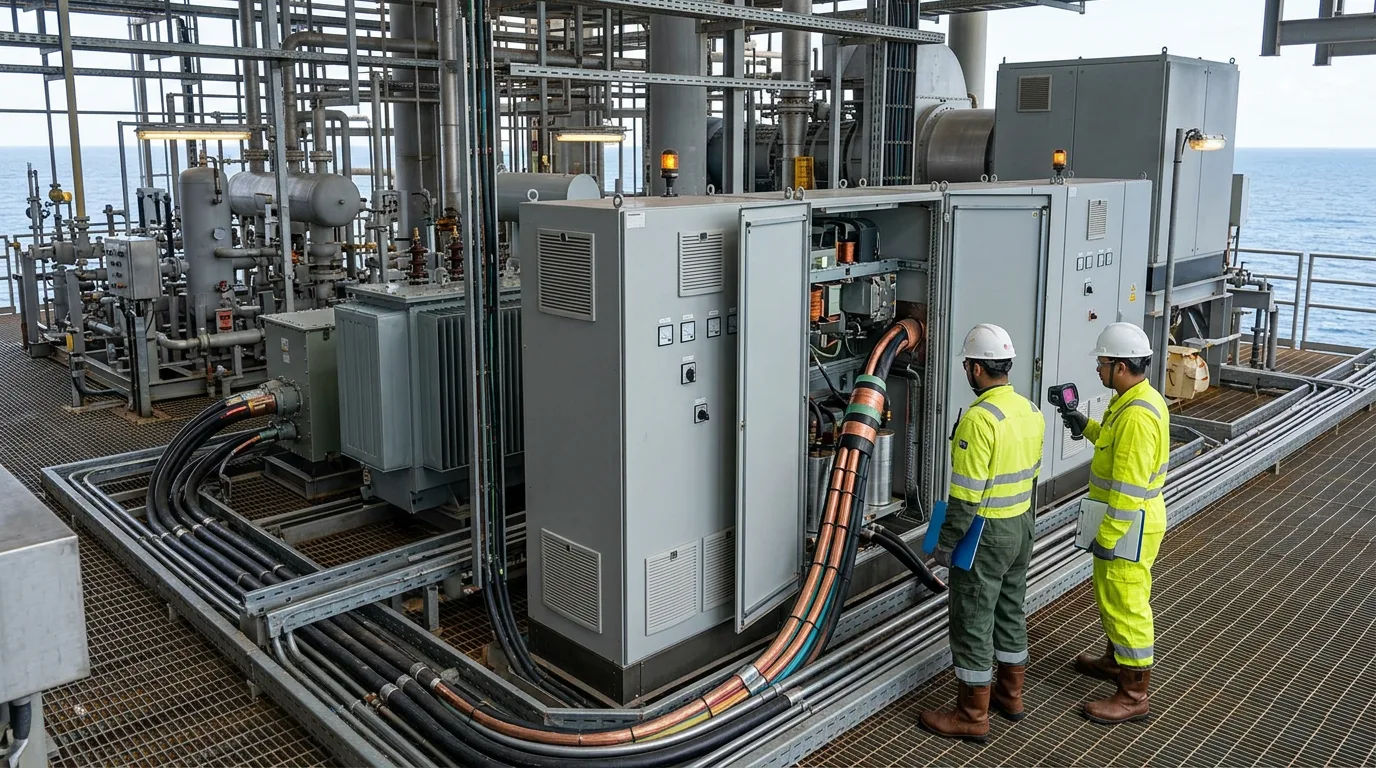
For hazardous-area topside pumps, put the filter in the safe area wherever you can. Confirm with the motor certificate and the drive supplier that the complete combination is covered for converter-fed operation.
Illustrative example: why long cables matter
This is an illustrative calculation with assumed ratios, not field data.
- Assume the motor's high-frequency impedance is ten times the cable surge impedance: Zl = 10 Zc.
- Reflection coefficient: Γ = (10Zc − Zc) / (10Zc + Zc) = 9/11 = 0.82.
- Peak terminal voltage: Vpeak = Vdc × (1 + 0.818) = 1.82 × Vdc.
- For a diode-rectifier front end at no load, Vdc = √2 × VLL, where VLL is the rms line-to-line supply voltage. Then Vpeak = 1.82 × 1.414 × VLL = 2.57 × VLL.
- The theoretical ceiling at Γ = 1 is 2 × Vdc.
Under these assumptions, the motor insulation sees a peak well above what the same motor sees on a sinusoidal supply, and it sees that peak on every switching edge. To judge it against a limit, check it against the motor manufacturer's declared withstand and the insulation-qualification basis in IEC 60034-18-41 or NEMA MG 1 Part 31. I haven't assigned a pass/fail number here, because that limit belongs on your motor datasheet.
A filter that lengthens tr raises lc, because lc = (tr × v) / 2. Once lc exceeds the actual cable length, the reflection no longer builds to full strength. That is the logic behind a filter-supported cable-length limit.
Practical checklist
- Get the drive's output rise time or dV/dt, and the manufacturer's cable-length guidance, for the exact drive and motor model.
- Confirm whether the motor insulation is inverter-duty, and what peak voltage and rise time it is qualified for under
IEC 60034-18-41orNEMA MG 1Part 31. - Calculate lc from the formula above using the cable's actual propagation velocity, and compare it with the installed cable length.
- For ESP, decide where the filter sits relative to the step-up transformer, and check resonance and magnetising behaviour with the supplier.
- Map surge protection in stages from service entrance to drive input, with separation and lead lengths recorded on the drawings.
- Confirm SPD ratings against the system voltage and earthing arrangement per
IEC 61643-11. - Protect instrument, communication and remote-control circuits at the drive.
- For hazardous-area motors, verify the certificate covers converter supply with the specified drive and filter.
- Keep the wellhead junction box vented, and don't change the arrangement without engineering review.
- Record baseline insulation resistance and motor current signature at commissioning, and trend against that baseline rather than against generic limits.
- Review SPD status indicators and replace degraded modules during planned outages. Before any work on equipment in a classified area, apply isolation, LOTO, verification of zero energy and gas testing as the site permit system requires.
Conclusion
Treat input surges and reflected-wave overshoot as separate problems with separate solutions. SPDs staged from the service entrance to the drive input handle the first. Output filtering matched to cable length and motor insulation handles the second. For ESP service, where the motor can't be reached after installation, put the design effort into the filter-transformer interaction and the cable-length check up front.
Your next step is to collect the drive rise-time data, the motor insulation qualification and the cable details for each installation. Calculate lc, and compare the result with the manufacturers' stated limits. Then audit each feeder for staged SPD coverage before the next planned outage.