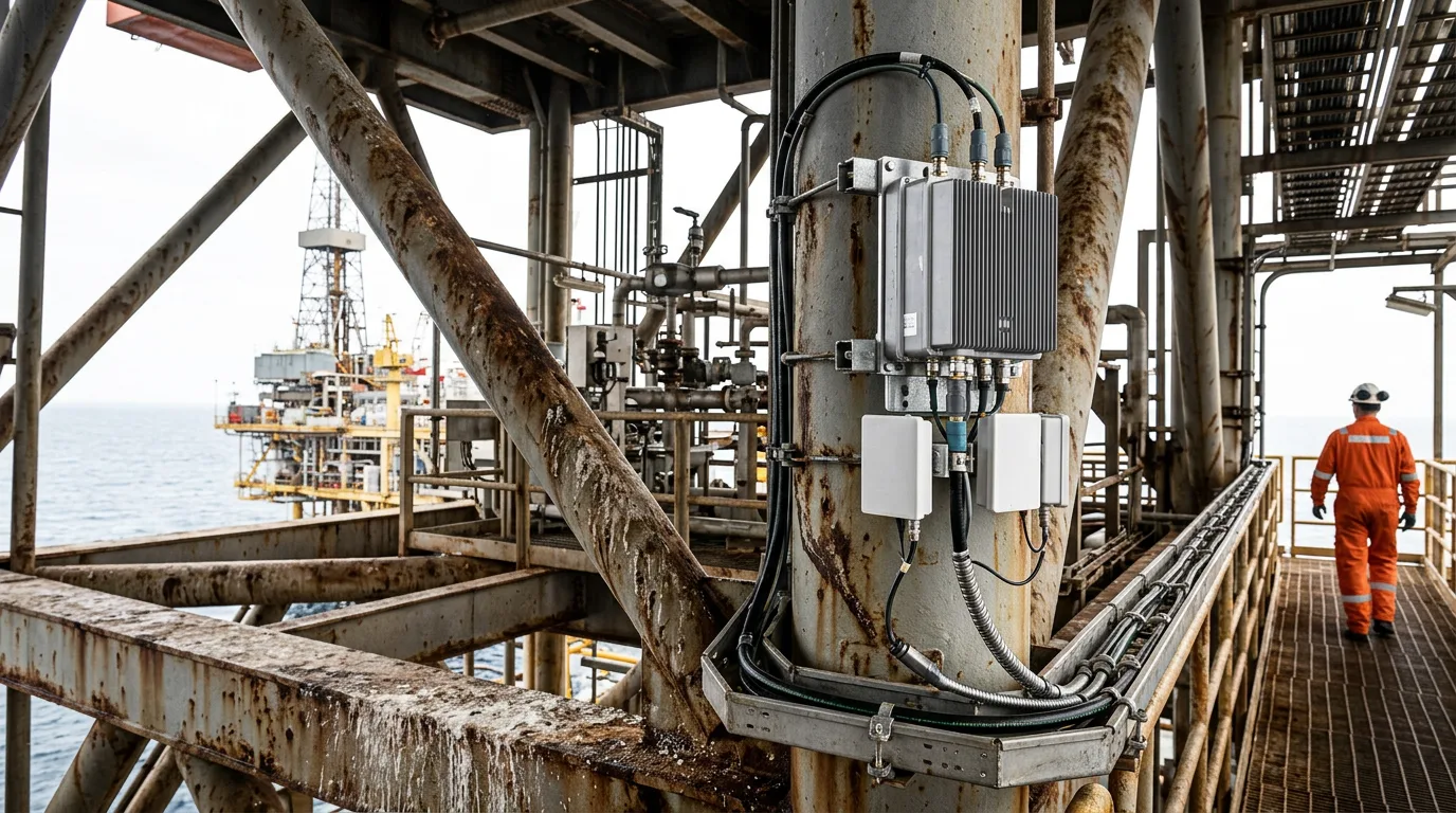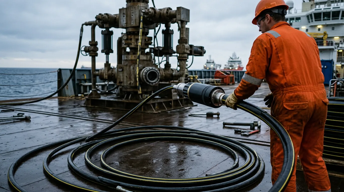
Deepwater tree control and monitoring run on optical fibre, and once that fibre is on the seabed it is expensive to reach. A bad fibre path usually shows up as something small: communication with the subsea control module drops in and out, sensor data goes missing, or the controls system quietly fails over to a backup path and hides the real fault. Fixing it means vessel time, ROV time and, if a termination has to be replaced, a planned intervention. Most of that cost is locked in during design, handling and commissioning. Installation discipline and a proper baseline matter far more than any troubleshooting you do later.
Standards and requirements context
Nothing on its own covers fibre on a subsea tree. The requirements come from several layers:
ITU-T G.971(12/2024), General features of optical fibre submarine cable systems, covers the characteristics of optical fibre submarine cable systems. It is a telecom-system reference. Use it for terminology, system architecture and fault-management concepts, not as a tree-equipment specification.ISO 13628-5, the subsea umbilicals part of the ISO 13628 series on subsea production systems, governs umbilicals that carry fibre to the tree's control system.- The applicable API and ISO subsea production control system standards cover the control system that terminates the fibre.
- Operator specifications add project-specific rules. Petrobras' technical specification I-ET-3010.00-5512-762-PPT-003, Infrastructure for Submarine Optic Network, is one example. It defines the submarine optical network infrastructure it expects contractors to deliver.
- For telecom-style seabed cable networks, the Enhanced ASEAN Guidelines for Strengthening Resilience and Repair of Submarine Cables set out regional best practice on protection, maintenance and repair. They are not oilfield standards, but their repair-readiness logic transfers well.
Where documents disagree, the project specification and the tree and control-system vendor's qualified interface drawings win. Use the telecom references to tighten your process, not to override qualified equipment limits.
Where fibre sits in the deepwater tree system
Fibre reaches a tree by two routes, and the maintenance approach differs for each.
- Umbilical-integrated fibre. Fibre elements run in the control umbilical from the host facility to a subsea umbilical termination, then through jumpers to the tree-mounted control module.
- Seabed fibre network. A telecom-style cable links host facilities and subsea hubs, with branches to field infrastructure.
Shore-end practice matters for the network case too.
The tree-side fibre covers the communication path to the control module and, where fitted, fibre-based sensing. Both face the same failure mechanisms: mechanical damage during handling, water ingress at terminations, connector contamination, and strain from tension or bending.
Decide what you will monitor before you lay anything. Tree projects need that discipline more than most.
- Confirm the fibre type and loss budget against the control-system vendor's interface requirements, not just the cable data sheet.
- Fix the optical test plan before lay: which tests at the factory, after spooling, after deployment, after termination, after tree connection.
- Record a dated factory baseline for every fibre in every length, including spares. Spare fibres are your repair margin, and an untested spare is not a spare.
- Agree the as-laid reporting format in advance so route position, touchdown and burial data can be matched to later fault-location results.
Handling and lay
Cable-ship practice, as described in the TE SubCom presentation on cable laying and repair operations, is built around controlled payout, continuous monitoring and a recorded as-laid position. The same principles apply to umbilical installation vessels.
- Tension and bend control. Fibre doesn't tolerate strain the way copper does. Respect the manufacturer's tension and minimum bend limits through every sheave, chute, carousel and hang-off. Don't work from memory. Take the limits from the qualified data sheet.
- Optical monitoring during lay. Keep the fibres under continuous or frequent optical observation so a handling-induced fault gets caught while the cable is still on deck or near surface.
- Touchdown and slack management. Plan touchdown near the tree and subsea termination so no residual tension or free-span loading reaches the termination.
- Protection near the tree. Specify protection, burial or mattressing for the final run, matched to the field's dropped-object and fishing risk.
Termination and subsea connection
The quality of the termination matters more to long-term reliability than the cable does.
| Connection approach | Where used | Strength | Main risk |
|---|---|---|---|
| Factory-terminated, dry-mated at topside | Host facility end | Controlled environment, easy inspection | Contamination during mating, bend damage at the termination unit |
| Factory-terminated, pressure-compensated with ROV-mated optical connector | Subsea termination to tree jumper | Allows installation without re-splicing | Particulate or fluid contamination, alignment and latching faults |
| Spliced and potted at a penetrator | Inside control module or termination housing | Compact and robust when well made | Splice quality is fixed at build and cannot be fixed in the field |
Whatever the approach, inspect and clean every end-face before mating, and keep dust caps on until the moment of connection. Photograph or record the end-face condition for the file. A connector that passes at the surface can still fail after pressure and thermal cycling, so keep the surface test data as a baseline for comparison.
Commissioning
Commissioning has to produce a baseline that later maintenance can actually use. After the tree is connected, run end-to-end optical tests on every fibre from the host facility. Record the trace, the loss profile and the event positions. File the traces with the cable identifiers, the as-laid report and the connector inspection records. Without that package, you can't tell later whether a trace feature is new.
Maintenance and monitoring
Condition monitoring
Monitoring should answer one question: is the link changing? Review articles on submarine cable systems and industry guides on repeaters and monitoring systems land on the same principle. Monitor continuously or periodically, and always against a known state.
- Trend received optical power and link-quality indicators from the control system against the commissioning baseline. Chase sustained drift rather than waiting for an alarm.
- Run periodic reflectometry on spare or dark fibres, and on live fibres where the architecture allows it. Compare each trace with the baseline.
- Correlate optical events with operations. Intervention work, ROV activity near the tree, dropped objects, anchoring and weather can all come before a change.
Fault localisation
When a fault appears, work from the top down.
- Confirm whether the fault is in the topside patching, the umbilical or cable, the subsea termination, or the tree-side jumper and control module.
- Take a reflectometer trace and compare it with the baseline. A new loss event at a known position points to a location. A complete loss of signal beyond a position suggests a break.
- Reconcile the position with as-laid data. Optical length is not route length, so allow for the cable's construction and slack, and apply the vendor's correction factors.
- Check the control-system side before committing assets. Module faults can look exactly like cable faults.
Repair strategy
Repair planning belongs in the design phase. The ASEAN guidelines were written to streamline protection, maintenance and repair, and their central point holds here: repairs go faster when permissions, spares, vessels and procedures are agreed in advance. For tree-related fibre:
- Keep qualified spare jumpers, connectors and termination parts in controlled storage, with their test records.
- Pre-agree the intervention vessel and ROV arrangements, including the tooling needed to demate, clean and remate optical connectors.
- Prefer replacing a jumper over repairing a cable in place, wherever the architecture allows.
- For seabed telecom-type cables, cable-ship repair practice (recover, cut, test, splice, re-lay) is well established. For umbilicals, the repair method is project-specific and should be defined with the manufacturer before installation.
Safety
Optical work at the tree normally doesn't open a hydrocarbon boundary. The interfaces still sit close to pressure-containing equipment, though, so the limits need to be written down.
- Don't open, disturb or disconnect any hydrocarbon-containing component as part of a fibre task. If the scope changes to require it, stop and raise a new work permit.
- Where that work becomes necessary, the permit must cover isolation, depressurisation, verification of zero energy, lock-out/tag-out, hazardous-area precautions, gas detection and safe venting to a defined location.
- Topside termination and test equipment on the host facility sit in classified areas. Use test equipment certified for the area, and apply hot-work and ignition-source controls.
- Treat optical test sources as laser hazards. Never look into a fibre end or connector, and confirm the source is off before you inspect.
- Confirm the tree and control system are in a safe state, and that the controls team has authorised the link outage. Losing communication can affect valve status indication.
Illustrative scenario
This scenario is constructed for guidance, not a reported event.
A deepwater tree shows intermittent loss of communication with its control module, and the control system keeps switching between its primary and secondary paths. The team compares live link-quality data with the commissioning baseline and finds a slow drift on the primary path that started after a nearby ROV campaign.
They run a reflectometer trace on the primary fibre and compare it with the stored commissioning trace. The trace shows a new loss event close to the subsea termination, and the rest of the route matches the baseline. A trace on a spare fibre in the same cable shows no such event, which points to the tree-side jumper and connector rather than the umbilical.
The team inspects the connector records and plans a jumper replacement using a pre-qualified spare. The ROV demates, inspects and cleans the end-faces before remating. After remating, they repeat the end-to-end test, and the trace matches the baseline again. They store it as the new reference, along with the contamination finding, and add a pre-mate inspection requirement to future ROV procedures.
Three practices made the difference: a baseline existed, a spare fibre let the team isolate the fault, and a qualified spare jumper was already on hand.
Practical checklist
Design and procurement:
- Fibre type, loss budget and connector types match the control-system vendor's interface documents.
- Applicable umbilical and subsea production control standards are listed in the specification.
- Repair spares, tooling and vessel arrangements are defined before installation.
Installation:
- Tension and bend limits are taken from the qualified data sheet and briefed to the deck crew.
- Fibres are optically monitored during handling and lay.
- Every end-face is inspected and cleaned before mating, and records are kept.
- Touchdown and final-run protection are designed so no loading reaches the termination.
Commissioning:
- End-to-end traces and loss profiles are recorded for every fibre, including spares.
- Traces are stored with cable identifiers, as-laid data and connector inspection records.
Operations:
- Received power and link-quality data are trended against the baseline.
- Reflectometry is repeated periodically and after any event that could load the cable.
- Optical events are correlated with ROV, vessel and weather activity.
Intervention:
- The permit scope excludes opening hydrocarbon-containing equipment unless a separate controlled permit is raised.
- Laser safety and hazardous-area controls are in place for topside testing.
Conclusion
Reliable fibre on a deepwater tree comes from baselines, controlled handling, clean terminations and repair readiness. It doesn't come from late-life diagnostics. Before the next installation or intervention, confirm that every fibre has a recorded commissioning trace, that spare jumpers and tooling are qualified and accessible, and that connector inspection is a required step in ROV procedures. Use ITU-T G.971 and the telecom repair guidance to sharpen your processes, and let ISO 13628-5, the control-system standards and your operator specification set the equipment limits. On existing fields without a baseline, create one at the next safe opportunity. Every later fault will be harder to diagnose without it.