The operational problem
An FPSO turret is the one point where all the station-keeping load, the riser system and the production fluids pass. If it underperforms, the vessel can't weathervane freely, and the bearing and swivel stack gets overloaded. The fixes are slow. Replacing a turret bearing or re-tensioning a mooring spread offshore means a long, weather-dependent intervention, and the production loss during it is the biggest cost. In harsh-environment deepwater fields the margin for error shrinks further: bigger line loads, more risers, and a vessel that has to hold a safe heading through extreme storms for its entire field life.
A trade journal review of turret engineering notes that increasing water depths and harsh-environment applications are pushing turret engineering to new levels of complexity, and that (offshoreindustry.co.uk, FPSO Turret Mooring Systems: Internal vs External Design, Bearings & Swivels). This article covers the design choices that decide whether a new-build turret avoids that outcome: weathervaning behaviour, bearing load paths and mooring line selection.
Standards and requirements context
The core framework for new-build design is a small set of documents:
API RP 2SK, Design and Analysis of Stationkeeping Systems for Floating Structures. It covers mooring analysis for intact, damaged and transient conditions.ISO 19901-7, Stationkeeping systems for floating offshore structures and mobile offshore units. It is the international counterpart for mooring design and analysis.API RP 2FPS, Planning, Designing, and Constructing Floating Production Systems. It sets the system-level context for hull, mooring and risers.DNV-OS-E301, Position Mooring. It is the classification-society offshore standard for mooring systems.
Your classification society and the operator's metocean basis of design set the actual design return periods, safety factors and survey requirements. Take those from the project documents, not from memory. The turret bearing and swivel are usually designed to the class rules plus the operator's specification, so define the bearing load cases and acceptance criteria early in the contract.
Weathervaning principles
Why the vessel turns
A turret-moored FPSO is anchored at one point and free to rotate around it. Wind, current and wave drift forces act on the hull away from the turret. That creates a yaw moment, which swings the vessel until it settles at a heading where the net moment is small. In practice this is usually bow-to-weather, which minimises roll and keeps the loads on the mooring lowest.
Turret position and yaw behaviour
Turret location along the hull is a primary design variable.
- Turret far forward: the vessel has a long lever arm behind the pivot and a strong weathervaning tendency. Heading follows the weather closely, but the vessel is more exposed to slow yaw excursions when wind, waves and current are not aligned.
- Turret further aft: the vessel is less directionally stable, and heading control gets harder.
In harsh environments, wind, swell and current can arrive from different directions. A heading that lags or oscillates can put beam seas on the hull and raise mooring loads. The station-keeping study by Duggal, Heyl and Ryu (SOFEC, 2009), Station-keeping of FPSOs in Extreme Environments, addresses this problem. For checking yaw response, the tools are model testing and coupled time-domain analysis, not hand calculations.
What the engineer must carry forward
Weathervaning analysis feeds three downstream design inputs:
- The range of vessel headings relative to the mooring spread, which determines how many lines are loaded at once.
- The maximum offset, which governs riser design and the clearance between lines and risers.
- The loads at the turret interface, which size the bearing and structure.
Turret bearing loads
The load path
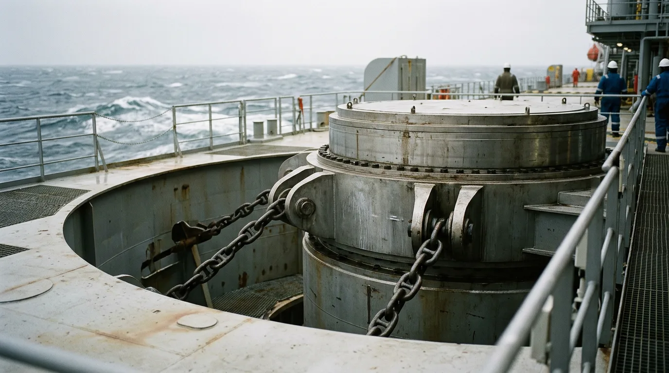
Mooring line loads enter the turret structure at the chain table or fairlead level, then pass through the bearing into the hull. The bearing has to carry horizontal loads, vertical loads and an overturning moment, and still rotate freely under load. Riser tension and dynamic riser loads add to the vertical component. (Offshore Magazine, Turret moorings evolve to accommodate complex subsea spreads, harsher environments), carries a heavy combined load. Those figures show how the harsh-environment design basis sets the scale of the bearing loads.
The key early question is how to split the load between the upper and lower bearing arrangement. That split sets moment capacity and structural stiffness, and it decides how tightly the hull can hold alignment under deflection.
Key design considerations
- Hull deflection and alignment: a bearing that is stiff on paper but sits in a flexing hull sees uneven roller loading. Specify the allowable ring flatness and hull-turret interface deformation as design inputs, then check them in global FE analysis.
- Extreme versus fatigue: the extreme storm case sizes the structure. Years of cyclic loading, though, drive wear and fatigue at the bearing and its supports.
- Damaged mooring condition: losing a line shifts load onto its neighbours and changes the load direction at the bearing. Run the bearing check for the damaged and transient cases from
API RP 2SK, not just the intact case. - Inspectability: a bearing you cannot inspect or maintain in place becomes a lifetime risk. Plan access, condition monitoring and a replacement or repair strategy during design.
Its core point still holds: the mooring, turret and vessel must be analysed as an integrated system, not as separate packages.
Turret configuration choices
| Aspect | Internal turret | External turret | Disconnectable buoy turret |
|---|---|---|---|
| Location | Inside hull, usually forward | Cantilevered from the bow | Buoy that latches into hull receptacle |
| Harsh-environment suitability | Strong; protected structure, high riser capacity | Generally for milder conditions | Used where the vessel must leave site |
| Riser capacity | High | More limited | Depends on buoy size |
| Hull impact | Large structural integration | Simpler hull modification | Receptacle and connection system |
| Main risk | Bearing and swivel access | Exposure to waves | Connector reliability, reconnection |
The Turritella paper (Design of the Disconnectable Buoy Turret Mooring for the Turritella FPSO, OTC, 2017) describes the Stones Field FPSO design and the challenges it posed for the disconnectable Buoy Turret Mooring. The disconnectable option adds mechanical complexity. But where the vessel must be able to leave the site, it can be the right answer.
Mooring line design choices
Line materials and configuration
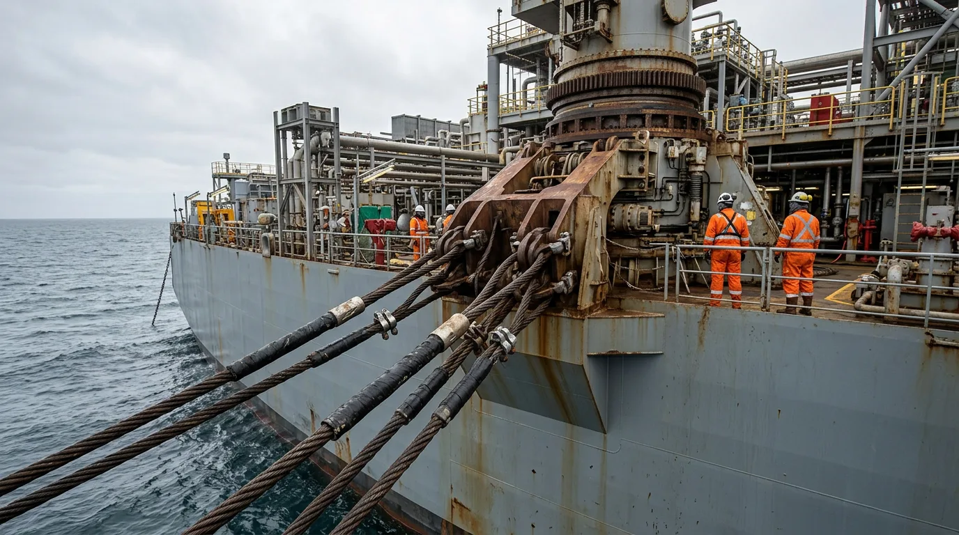
Deepwater changes the weight problem. Heavy all-chain lines add large suspended weight to the vessel, which loads the turret vertically and eats into payload. The usual responses are:
- Chain–polyester–chain: a taut or semi-taut arrangement. The polyester segment cuts line weight and gives a more compliant response, but it needs careful assessment of stiffness behaviour and handling.
- Chain–wire–chain: a more traditional catenary arrangement with a well-established track record. Wire lowers weight relative to chain but needs corrosion and fatigue management.
- Taut versus catenary: taut systems reduce footprint and vertical load, but they increase anchor uplift demand and make line tension sensitive to offset.
| Option | Weight on turret | Footprint | Main design concern |
|---|---|---|---|
| All-chain catenary | Highest | Wide | Vertical load, vessel payload |
| Chain–wire–chain | Moderate | Wide to moderate | Corrosion, fatigue in wire |
| Chain–polyester–chain (taut) | Lower | Compact | Anchor uplift, stiffness behaviour, installation |
Mooring and riser feasibility for a Gulf of Mexico FPSO in 10,000 ft water depth was examined in the 2005 OTC paper Mooring And Riser Design For GoM FPSOs In 10,000 Ft Water Depth. Its approach is the right one. The mooring and riser systems are designed together because they share the same offset envelope and the same turret.
Riser compatibility
Mooring stiffness sets vessel offset, and offset sets riser stress. Bluewater describes a dedicated design for accommodating steel lazy wave risers in the deepest oceans, with many risers, umbilicals and dynamic power cables supported on the same turret (Bluewater, FPSO and FLNG mooring). A mooring that restrains offset well may be needed to keep steel risers within their limits. A softer mooring reduces line loads but increases offsets. So the choice is a system optimisation, not a line-by-line decision.
Fatigue and damaged cases
In harsh environments, extreme storm loading often governs the strength check. Fatigue, meanwhile, governs the long-term integrity of chain connectors, fairleads and the turret structure around them. Check the following:
- Intact extreme and fatigue cases.
- A one-line-damaged case, with the resulting offset and load redistribution.
- Transient behaviour immediately after a line failure, which
API RP 2SKtreats separately from the steady damaged condition.
Illustrative scenario: choosing a mooring concept
This scenario is illustrative and does not describe a real project.
A project team is developing a new-build FPSO for a deepwater, harsh-environment field. The riser count is high, and steel lazy wave risers are preferred for the main production lines. The first mooring proposal is an all-chain catenary spread, mostly because the operator is familiar with it.
Global analysis shows two problems. First, the suspended chain weight pushes the vertical load on the turret bearing higher than the structural team accepted at concept stage. Second, the wide catenary footprint creates clearance concerns with the riser corridor.
The team moves to a chain–polyester–chain configuration. That cuts suspended weight and tightens the footprint. The new problems are higher anchor uplift demand and the need to confirm polyester stiffness and installation procedures. The turret structural team re-runs the bearing checks with the lower vertical load, and the riser team re-checks offsets with the new stiffness. The decision rests on the integrated results, not on a single package optimum.
Decision checklist
- Define the metocean basis, including wind, wave and current misalignment, before fixing turret position.
- Confirm turret location from yaw stability analysis, using model tests or coupled time-domain simulation.
- Establish bearing load cases for intact, damaged and transient mooring conditions.
- Specify hull–turret interface deflection limits and check them in global FE analysis.
- Require a bearing maintenance, inspection and condition monitoring plan before contract award.
- Review swivel and fluid transfer access. Any intervention on hydrocarbon-containing swivel or piping needs full isolation, depressurisation, verification of zero energy, LOTO, gas detection, hazardous-area precautions and safe venting under the permit-to-work system.
- Evaluate all-chain, wire and polyester options against turret vertical load, footprint and anchor uplift.
- Run the mooring and riser systems on a shared offset envelope and iterate between the teams.
- Check fatigue for connectors, fairleads and turret supports, not only line segments.
- Decide early whether disconnection is needed, since it changes the turret concept.
- Confirm applicable class and operator requirements against
API RP 2SK,ISO 19901-7,API RP 2FPSandDNV-OS-E301.
Conclusion
Turret and mooring design for harsh-environment deepwater FPSOs is an integrated problem. Turret position governs heading behaviour. Heading and offset govern line and riser loads. Those loads pass through a bearing that has to keep rotating for the field life. Treat the vessel, turret, mooring and risers as one analysis model. Make bearing inspectability a design requirement. And compare line materials on turret vertical load and riser offset, not just line cost.
As next steps, freeze the metocean basis and riser count. Run coupled analysis for two or three turret positions and mooring concepts. Then get the bearing supplier and class society involved before the load cases are fixed.