Operators converting natural gas transmission lines to hydrogen run into a problem that a standard pressure-capacity check will miss. Steel that has carried sour-free methane for decades can lose fracture toughness and crack faster under pressure cycling once hydrogen is at pressure against it. The damage gathers at the flaws, hard zones and seam welds that every old line carries. Get the assessment wrong and it costs you either way. Too optimistic, and you are running a crack-driven rupture risk on a line never designed for the duty. Too conservative, and you derate for no good reason or replace pipe that could have been qualified. Germany's network build-out has made this a routine question for integrity teams. The answer comes from material data, fracture mechanics and a clear picture of the line's pressure history.
Standards and requirements context
These are the usual anchors for a repurposing case.
ASME B31.12covers hydrogen piping and pipelines. It offers a prescriptive route and a performance-based route for existing pipelines. Hydrogentechworld describes the performance-based route (Option B) as relying on fracture mechanics qualification testing and Engineering Critical Assessment (ECA). Used that way, it can justify an operating pressure with potentially no reduction in allowable pressure.ASME B31.8covers gas transmission and distribution piping systems. It is the baseline code for the line's existing design and integrity management.API 5Lis the line pipe specification. It defines the grades, manufacturing routes and test requirements you will compare your mill records against.API 579-1/ASME FFS-1is the fitness-for-service standard for flaw assessment.BS 7910is the guide to methods for assessing the acceptability of flaws in metallic structures.ASTM E1820covers measurement of fracture toughness, andASTM E647covers measurement of fatigue crack growth rates. Both underpin hydrogen-environment test programmes, with the gas environment and loading arrangements set out in the test plan.
None of these removes the need for project-specific testing. A prescriptive route is faster, but it is conservative. A performance-based route costs test time and engineering effort, and that is where retained capacity is won or lost.
Why hydrogen changes crack behaviour in linepipe steel
Mechanism in brief
Molecular hydrogen splits into atoms on clean steel surfaces, and those atoms diffuse into the lattice. They build up at stress concentrations (crack tips, notches, corrosion features) and at microstructural traps. Penspen puts the consequence simply: ductility falls, and the steel becomes more prone to crack initiation and growth. Fracture toughness, fatigue resistance and even strength can all move.
For an integrity engineer, the practical effects come down to three things:
- Reduced fracture toughness in the presence of a flaw. A defect that was benign in natural gas may now sit much closer to its critical size.
- Accelerated fatigue crack growth under pressure cycling. This is usually the governing concern for lines that follow variable supply or demand, because cycling keeps driving sub-critical growth of existing flaws.
- Little effect on stable, flaw-free pipe body in many cases. The risk is flaw-driven, which is why the inspection record carries so much weight.
Where the risk concentrates
Hydrogen sensitivity isn't uniform along the line. Scrutiny should go first to:
- Girth welds and their heat-affected zones, especially older welds with harder microstructures.
- Longitudinal and spiral seam welds, particularly from vintage processes with known seam-flaw histories.
- Crack-like features from manufacture or service: stress-corrosion cracking colonies, lack-of-fusion, hook cracks and cold-cracking remnants.
- Corrosion pits and dents, where local stress raising lets hydrogen accumulate and take up cyclic strain.
- Fittings, valves and tie-ins, where properties are often poorly documented and local hardness may be high.
Grade and microstructure
The literature leans towards lower-strength steel as the safer choice. It also points out that high-strength steels offer a substantial cost benefit, which is why the question matters commercially. With major modifications, higher-strength steel may still be usable.
Parker et al. (Metals, 2026) go further and treat microstructure as a driver of repurposing decisions. Two pipes of the same nominal grade can behave differently depending on their ferrite-pearlite balance, the presence of bainite or martensite, banding, inclusions and local hardness.
So grade is a screening variable, not a verdict. The decision should rest on measured toughness and crack growth data for the actual steel, in the actual gas environment.
Assessment methods
Records review and segmentation
Start with the paper. Pull together mill certificates, pipe specifications, seam type, vintage, welding procedures, hydrotest history, in-line inspection (ILI) runs, dig reports, repair history, and the pressure-cycling record from SCADA. Then segment the line by pipe population (manufacturer, grade, wall, seam type, vintage) rather than treating it as one asset. Gaps in the records are where unexpected variability hides.
Material verification and characterisation
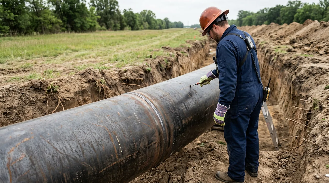
Where records are incomplete, confirm properties by sampling. Test strength, chemistry, hardness and microstructure on representative pipe and welds. Hardness mapping across weld HAZs is useful for finding local hard zones. Microstructural examination connects those results to the susceptibility concerns Parker et al. raise.
Hydrogen-environment mechanical testing
Testing in hydrogen gas is the core of a performance-based case. It typically includes:
- Fracture toughness testing in hydrogen at relevant pressure (
ASTM E1820framework). - Fatigue crack growth testing in hydrogen across a range of load ratios and cycle frequencies (
ASTM E647framework). - Tensile testing in hydrogen to measure ductility loss.
Test pressure, gas purity, loading rate and specimen orientation all have to match the service case. Hydrogen results are sensitive to every one of these, so a test report that leaves them out is of limited value. Measure first, then calculate.
Engineering critical assessment
An ECA takes the measured hydrogen-environment toughness and crack growth data, the flaw population (from ILI, hydrotest margin, or assumed manufacturing flaws) and the actual load spectrum, and works them together. The outputs are:
- Critical flaw sizes at the proposed maximum operating pressure.
- Fatigue life or remaining life for the governing flaws under the cycling the line will actually see.
- Required inspection intervals and flaw-detection capability.
Blend and pure-hydrogen cases should not be assessed interchangeably. Partial pressure of hydrogen is the driver, not just volumetric fraction.
Comparing the two qualification routes
| Aspect | Prescriptive route | Performance-based route |
|---|---|---|
| Basis | Code-defined conservative factors | Hydrogen-environment testing plus ECA |
| Data needed | Basic material and design data | Toughness and fatigue crack growth data, flaw population, load spectrum |
| Pressure outcome | Often a reduction on existing lines | Potentially no reduction, if the ECA supports it |
| Effort and lead time | Lower | Higher, with test programme and analysis |
| Best suited to | Short sections, uncertain records, or quick conversion | Long-distance lines where retained capacity has high value |
Typical mitigation steps
Once the assessment shows what governs, mitigation generally takes one of these paths:
- Limit pressure cycling. If fatigue crack growth governs, cutting the amplitude and frequency of pressure swings often extends life more than lowering maximum pressure does. Line-pack management and storage buffering are the operational levers.
- Reduce maximum operating pressure where the ECA or the prescriptive route requires it.
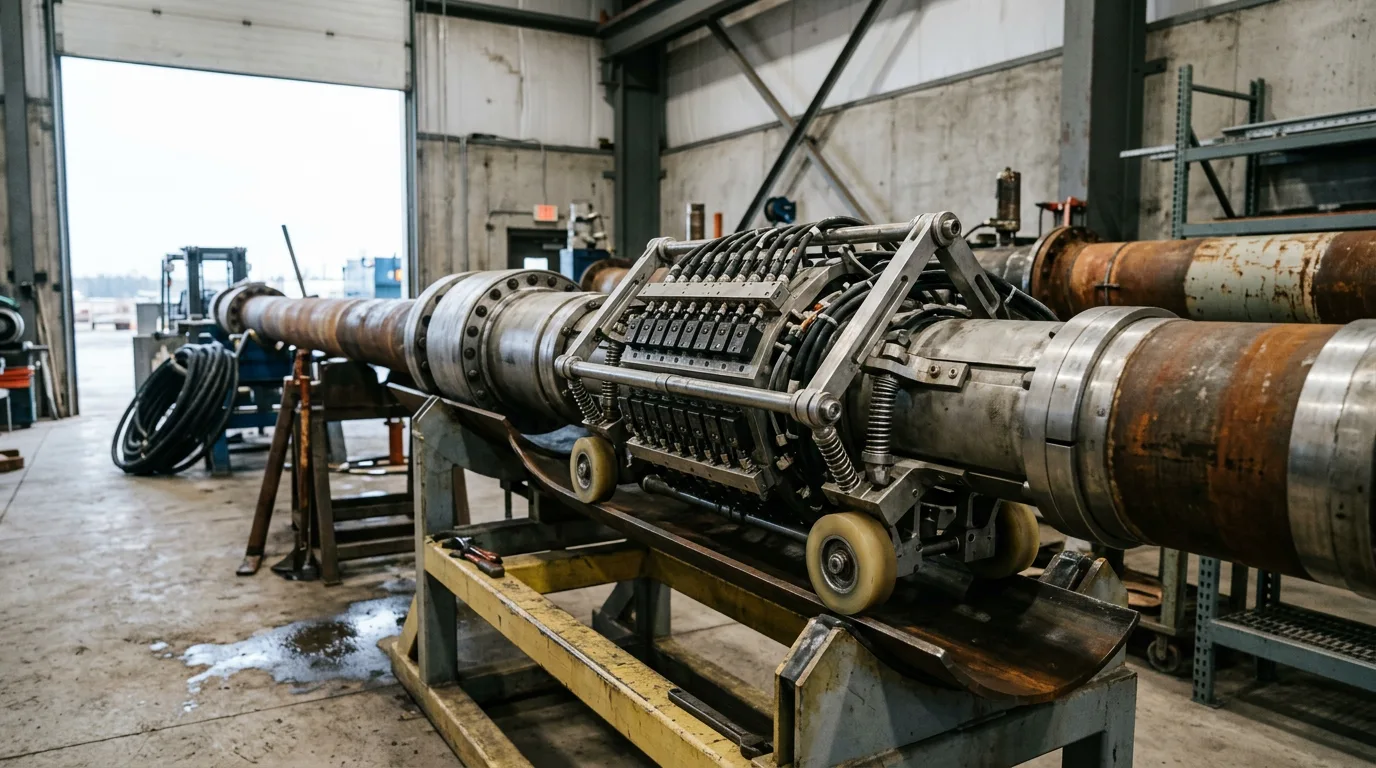
- Targeted ILI for crack-like flaws. Ordinary metal-loss tools won't be enough. Use crack-detection technology matched to the seam and girth weld features you identified, and set reinspection intervals from the ECA's crack growth results.
- Repair or replace sections with unacceptable flaws, hard welds or poorly documented fittings. Replacing a limited number of sections can unlock the rest of the line.
- Control gas composition. Gas purity and trace constituents influence hydrogen uptake. Set composition limits only on the basis of test evidence for your steel, not general assertion.
- Hydrotest or other proof strategies to bound flaw size. Interpret them with care, because a pressure test does not demonstrate cyclic performance in hydrogen.
- Monitor and update. Treat the first years as a verification period, with actual cycling data feeding back into the ECA.
Illustrative scenario
This scenario is constructed for illustration and is not a reported project.
An operator wants to convert a long natural gas transmission line to hydrogen. The line has two pipe populations: an older section with a vintage seam weld and sparse mill records, and a newer section with full documentation. Operations expects significant pressure cycling, because supply will follow variable production.
The team segments the line first. For the newer section they sample, test and run an ECA. The measured hydrogen-environment data supports the intended pressure, but the fatigue calculation shows that cycling amplitude governs the inspection interval. The operator therefore sets cycling limits and plans crack-detection ILI at intervals derived from the calculation.
The older section is a different story. Missing records and the seam type leave too much uncertainty. The team has two options: fund a larger test programme, or replace the section. Because the section is short compared with the whole line, they choose replacement. The performance-based route is applied where it pays off and dropped where it doesn't. A single approach across the whole line would have been either wasteful or unsafe.
Practical checklist and decision guidance
Screening and data:
- Segment the line by pipe population, seam type, vintage and weld procedure.
- Confirm mill and weld records. Where they are missing, plan verification sampling.
- Collect ILI, dig, hydrotest and repair history, plus actual pressure-cycling data.
- Identify crack-like features and hard zones as priority locations.
Qualification:
- Decide between prescriptive and performance-based routes on the basis of line length, retained capacity value and record quality.
- Specify hydrogen-environment toughness and fatigue crack growth tests that match service pressure, purity and loading.
- Perform an ECA with the real flaw population and cycling spectrum.
- Check that the ECA covers girth welds, seam welds and fittings, not just pipe body.
Operations and mitigation:
- Define cycling limits and a pressure management philosophy.
- Select crack-capable ILI and set intervals from ECA crack growth results.
- Plan repair or replacement of sections that fail assessment.
- Review results against operating experience and update the ECA.
Field safety for any sampling, cut-out, dig or inspection of hydrocarbon-containing pipe:
- Isolate the section positively, using a proven double-block arrangement or physical disconnection.
- Depressurise through a controlled, designed vent route, and verify zero energy with gauges at the work location.
- Apply LOTO to all isolation points and energy sources.
- Classify the work area for hazardous atmospheres, and use certified equipment and ignition-source controls.
- Run continuous gas detection covering hydrocarbons, and hydrogen where present. Remember hydrogen's wide flammable range and low ignition energy.
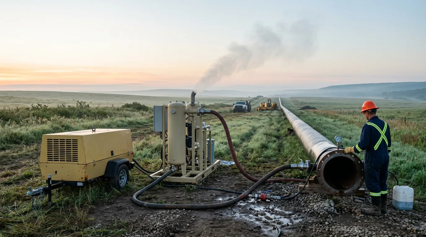
- Vent and purge to a safe location, and confirm gas-free status before cutting or hot work.
Conclusion
Repurposing is neither automatically safe nor automatically unviable. Grade is a useful screen, but the evidence points to microstructure, weld condition, flaw population and pressure cycling as the controlling factors. The practical path is to segment the line, close the records gaps, test the real steel in hydrogen, and run an ECA on the actual flaws and loads. Next step: choose the qualification route for each segment before committing to a test programme, and use the first results to decide where replacement is cheaper than further testing.