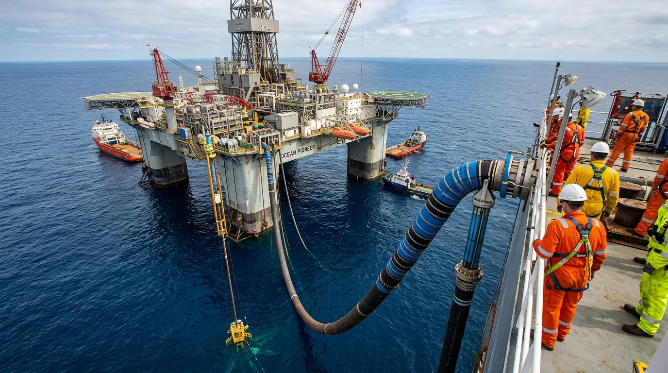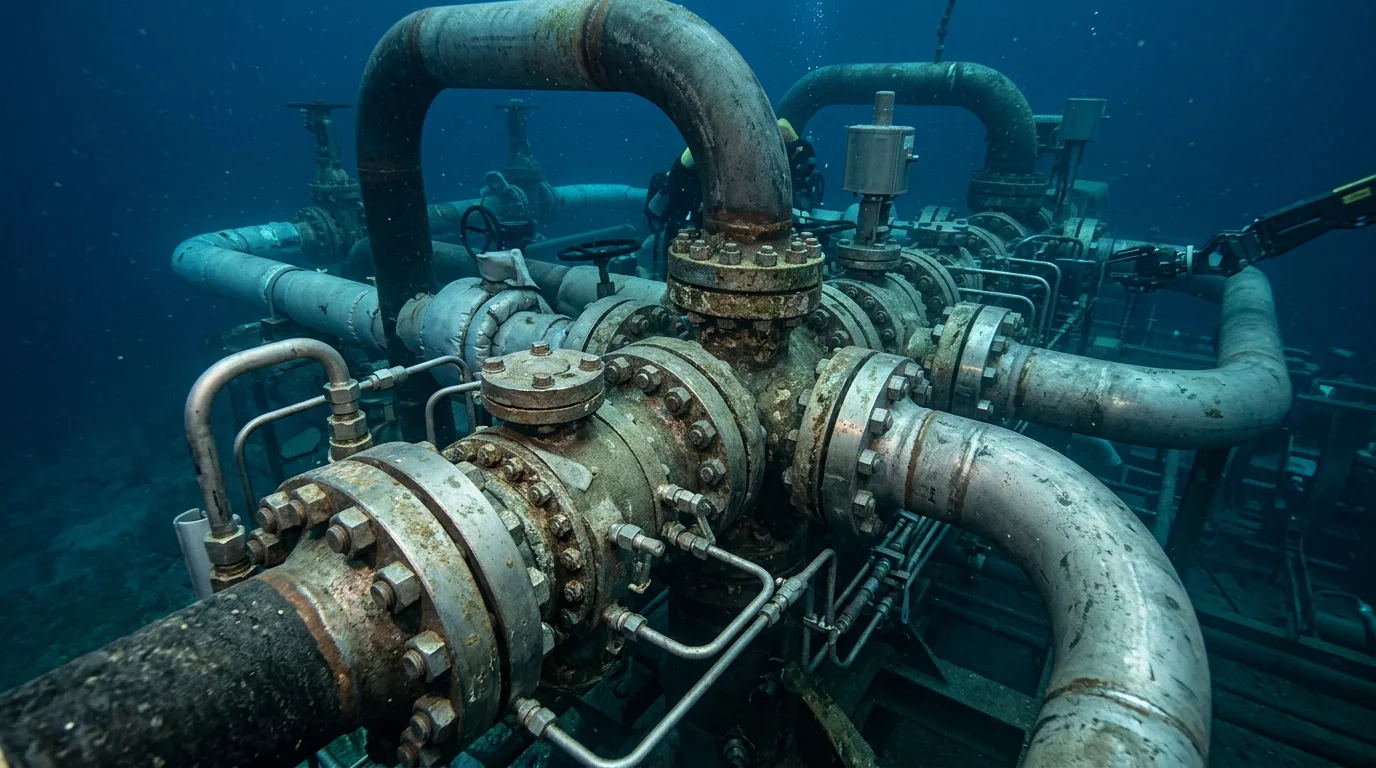
Near-host discoveries look easy on a map. A small accumulation sits close to an existing platform or FPSO, so you assume a short flowline and a control umbrella will do the job. The trouble shows up later. The fluid cools in a long flowline, the host's topsides turn out to be full, or a poor riser or manifold choice locks in a slugging problem for the rest of field life. Marginal fields are often too small to carry a standalone facility, so tieback economics are fragile. One flow assurance surprise after sanction, such as an undersized chemical line, a hydrate-prone shutdown profile or a host that cannot take the produced water, can wipe out the margin that justified the project. This article covers how to test those limits early: distance and pressure, host selection, chemical injection, and the riser versus manifold choice.
Standards and requirements context
Few standards govern the tieback concept itself. You assemble the design basis from system, pipeline and component documents:
ISO 13628-1covers design and operation of subsea production systems, with general requirements and recommendations. It is the framework for field architecture, interfaces and operability.ISO 13628-5covers subsea umbilicals. It applies to the electrical, hydraulic and chemical injection lines that decide how much chemical you can deliver, and how quickly, at the far end of a tieback.DNV-ST-F101covers submarine pipeline systems. It governs flowline and rigid riser design, including pressure containment, and sets the wall thickness and insulation envelope you carry into thermal calculations.- Flexible risers and flowlines are covered by the ISO 13628 series part for flexible pipe systems and by the applicable API recommended practice. Check that the revision your supplier quotes matches the one in your contract.
The host's own safety case, process design basis and chemical discharge permits also act as requirements. In practice they often constrain the tieback more than any pipeline code does.
Distance and pressure limits
What actually sets the limit
There is no universal maximum tieback length. The limit is wherever one of four constraints becomes binding first:
- Thermal. During steady flow, fluid has to reach the host above hydrate formation and wax appearance conditions. The system also has to stay manageable through shutdown and restart.
- Hydraulic. Reservoir drive, plus any subsea boosting, has to overcome friction and hydrostatic losses and still deliver the required arrival pressure at the host inlet.
- Chemical delivery. Umbilical or dedicated injection line capacity and response time have to support inhibitor dosing and its turn-down.
- Control and power. Signal integrity, hydraulic response and electrical supply have to hold over the full offset.
Industry work is pushing the envelope. An OTC paper on integrated solutions for 100 km deepwater liquid subsea tiebacks (2021) notes that tiebacks to existing hosts are among the most sanctionable development routes for oil discoveries. The same paper treats long liquid tiebacks as feasible only with an integrated approach across flow assurance, hardware and operations. Stretching a conventional design will not get you there.
Pressure considerations
Pressure sets the design envelope in two directions:
- Shut-in and design pressure. If the reservoir can shut in above the host-side flowline rating, you need either a flowline rated for shut-in conditions or a high-integrity pressure protection system at the subsea or host end. Weigh the cost of heavier wall pipe against the cost, testing burden and reliability case of the protection system.
- Arrival pressure. Low arrival pressure helps recovery but makes slugging, gas expansion and hydrate margin harder to manage. Hydrates form more easily at high pressure and low temperature, so the shut-in and cooldown case drives the inhibitor philosophy, not the steady-state case.
Treat the host's separator pressure and inlet capacity as fixed boundary conditions. The host rarely has the flexibility to change them.
Host selection
Hosts get picked on proximity alone, and that is the usual mistake. The feasibility framing in the Umbrex tieback analysis is a useful reminder: the aim is technical viability, cost-effectiveness and the best configuration of the connection, which is a wider question than shortest distance. The NeqSim TiebackAnalyzer takes the same view. It evaluates tie-back options that connect satellite fields to host facilities, so host and route get screened together rather than one after the other.
Screen candidate hosts on these points:
- Ullage and process capacity. Check gas handling, liquid handling, produced water treatment and export constraints separately. A host with spare oil capacity can still be limited by water handling or gas compression.
- Remaining life. The host has to outlive the tieback's production profile, or the project picks up a hidden life-extension cost.
- Fluid compatibility. Wax, scale, asphaltene and corrosion behaviour of the new fluid must suit the host's materials and chemicals. Commingling can cause problems that neither stream causes on its own.
- Riser and hang-off availability. Spare slots, tension capacity or porch space may decide whether a riser is practical at all.
- Utilities. Power, hydraulic supply, chemical storage and umbilical termination space set what the host can actually deliver.
- Operator and ownership interfaces. Tariffs, allocation metering and shutdown priority belong in the design basis. Leave them for later commercial negotiation and they will hurt you.
Flow assurance strategy
Thermal management
The main options are passive insulation, active heating (electrical or hot fluid), and operational methods such as inhibitor use and controlled shutdown and restart. On most near-host tiebacks, insulation plus chemical inhibition is enough. Active heating usually shows up when cooldown time has to stretch beyond what insulation can deliver, or when the distance makes inhibitor volumes impractical.
Hydrate and wax
Hydrate management typically relies on thermodynamic inhibitor injection at the tree or manifold, backed by insulation that buys time before hydrate conditions are reached. Wax management combines insulation, wax inhibitors or dispersants and, where the flowline allows, pigging. A pigging loop is a layout decision that is expensive to retrofit, so settle it at concept stage.
Slugging, whether terrain-induced or riser-induced, is covered in the riser section below.
If a blockage is suspected, remediation by depressurisation is a hydrocarbon-containing operation. It has to run under an approved procedure covering positive isolation, controlled depressurisation (ideally from both sides of the plug to avoid projectile movement), verification of zero energy, lock-out/tag-out, hazardous-area precautions, continuous gas detection and safe routing of vented or flared gas. Do not improvise it.
Chemical injection strategy
Chemical delivery is where long offsets often run out of room, because the umbilical is a physical, finite resource.
Design questions
- Which chemicals are continuous and which are batch? Hydrate inhibitor during startup and shutdown, scale inhibitor, corrosion inhibitor, wax inhibitor, demulsifier and asphaltene dispersant each have different delivery and turn-down needs.
- Where are the injection points? Tree, manifold and downhole injection each protect a different part of the system. Injecting at the manifold alone leaves the individual well jumpers and trees exposed on shutdown.
- Is dosing flexible? Per-well metering gives control but adds valves and failure modes. Shared headers are simpler but cannot trim dosing to individual well behaviour.
- Is line capacity sufficient at end of life? Water cut climbs, and the volume of aqueous-phase inhibitor climbs with it. Size for the late-life case.
- Is the chemical compatible with the host? Discharge permits and downstream process effects (emulsions, foaming, catalyst or membrane impacts) have to be cleared with the host operator before the umbilical is specified.
- What is the response time? Long, small-bore lines respond slowly. If the hydrate strategy depends on fast inhibitor delivery after a trip, test it against umbilical fill and pressure-drop behaviour, not against the pump's nameplate rate.
A dedicated hydrate line, redundant routing for critical chemicals and the ability to circulate inhibitor are common resilience features. Which ones you need depends on your cooldown margin, so size them from the thermal analysis rather than from precedent.
Riser versus manifold: tie-in architecture
Layout drives both operability and flow assurance, so the decisions that matter most for a near-host tieback are these.
| Decision | Direct tie to host riser | Subsea manifold with shared flowline |
|---|---|---|
| Best fit | Single well or small cluster close to the host | Multiple wells or phased development |
| Flowline count | One flowline per cluster, with more risers on the host | One trunk line, fewer host risers |
| Host riser demand | High, uses porch or hang-off slots | Low |
| Per-well monitoring | Direct, tied to the tree | Needs manifold instrumentation and choke strategy |
| Future expansion | Needs new risers | Add well slots or jumpers |
| Slugging exposure | Depends on riser and flowline geometry | Depends on trunk and riser geometry; wells commingle |
| Pigging | Needs a loop or a second line | Achievable at the manifold |
| Failure impact | Isolated to one flowline | A trunk line issue affects all wells |
Riser type
- Flexible risers tolerate host motion and are quick to install. They cost more per unit for large bores and harsher fluids, and they have a limit on size and pressure rating. Their insulation approach differs from rigid pipe, so confirm thermal performance with the supplier.
- Rigid risers (steel catenary, pull-tube or other configurations) suit higher pressures and larger diameters, but the host motion and fatigue envelope have to be acceptable.
- Riser base gas lift can reduce riser-induced slugging and lower hydrostatic head. The price is a gas supply line and more complexity.
The riser's geometry, with its low point and vertical rise, often drives slugging behaviour at the host inlet. Check slug catcher or separator capacity against transient simulation results, not just steady-state liquid loading.
Illustrative scenario
This scenario is illustrative and does not describe a real project.
A small oil discovery sits within reach of a mature host. The first concept connects two wells to the host with a single insulated flowline and a flexible riser. Screening shows steady-state arrival temperature comfortably above hydrate conditions. The shutdown case tells a different story. The cooldown time does not leave room for the full restart procedure, and the umbilical's chemical line is slow to get inhibitor to the far end.
Three options are compared:
- Thicker insulation. This improves cooldown but costs more per length and may need a different installation method.
- A larger-bore chemical line or dedicated hydrate line. This cuts response time but enlarges the umbilical.
- A modified operating philosophy, with a controlled depressurisation or inhibitor-displacement step after a planned shutdown.
Insulation alone does not resolve the unplanned trip case, so the team combines a modest insulation upgrade with a dedicated inhibitor line and a pre-agreed trip response. They also check that the host's separator can accept the transient liquid arrival from the riser. The sequence is the point. Shutdown and restart cases were tested before the architecture was frozen, and chemical response time was treated as a design variable alongside insulation.
Practical checklist
- Define the design basis: fluid properties, shut-in pressure, arrival pressure and profile over field life.
- Confirm host capacity separately for oil, gas, water and chemicals, and confirm remaining host life.
- Run steady-state, shutdown, cooldown and restart cases before selecting insulation or heating.
- Test chemical delivery response time and late-life volumes against the umbilical design.
- Confirm chemical compatibility and discharge acceptability with the host operator.
- Decide on pigging provisions at concept stage.
- Confirm shut-in pressure against flowline rating, or define the protection system and its reliability case.
- Check riser slugging and host inlet handling using transient simulation.
- Compare direct riser tie-in and manifold architecture on expansion, riser count and failure impact.
- Verify the revision of each applicable standard and align supplier scope to it.
- Write the hydrate remediation procedure, with isolation, depressurisation, zero-energy verification, LOTO, gas detection and venting, before first oil.
- Use screening tools, such as the NeqSim
TiebackAnalyzer, to compare host and route options, then confirm the shortlist with detailed simulation.
Conclusion
Near-host discoveries are still the most practical way to bring marginal volumes to production, but proximity alone does not make a tieback simple. Test the shutdown and restart cases first, size chemical delivery for late-life conditions, and treat host capacity as a multi-phase constraint. Pick the riser and manifold arrangement on expansion and failure consequences as well as capital cost.
Next, build a screening matrix of candidate hosts and routes. Run the thermal and hydraulic cases on the shortlist, then commission a transient study covering slugging and restart before concept select. Bring the host operator into the chemical and process interface discussions early, because their constraints often decide the final architecture.