Surge Analysis for Crude Export Terminal Loading Lines: Valve Closure Times and Relief Sizing
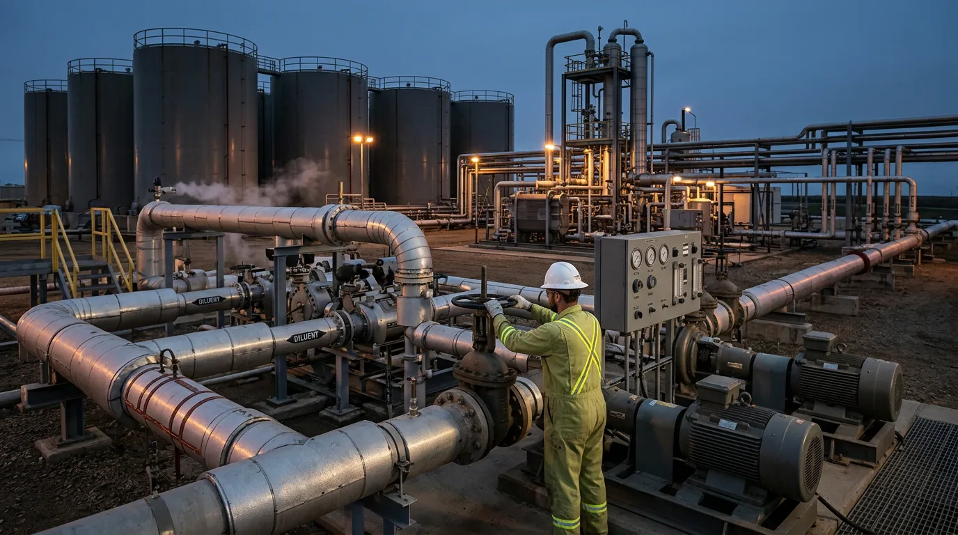
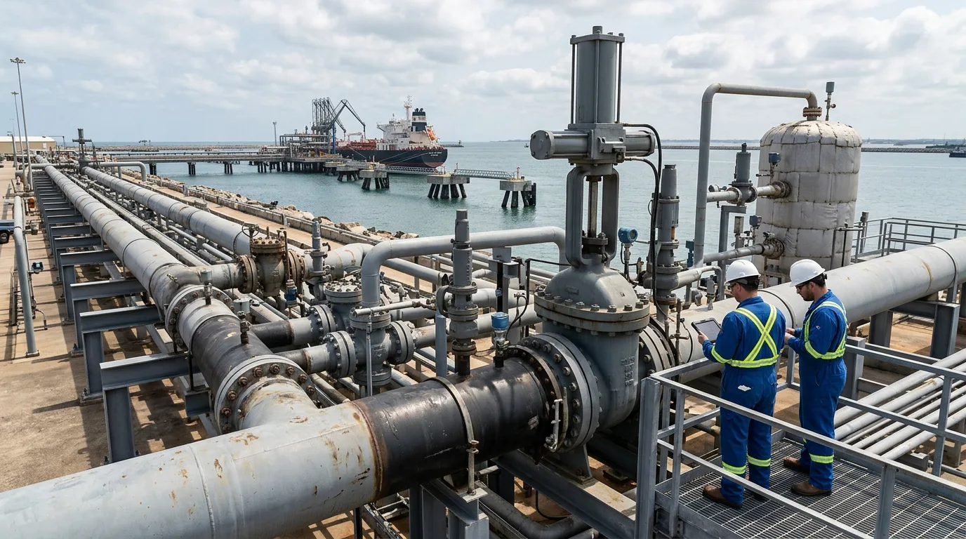
Crude export terminal loading lines routinely experience pressure transients that exceed the static design envelope. When an emergency shutdown valve closes abruptly on a large-diameter loading arm or manifold header, the kinetic energy of a moving crude column converts instantaneously to pressure — a phenomenon engineers call surge, or water hammer. The consequences range from flange leaks and check-valve slam to catastrophic pipe rupture, spill containment activation, and tanker departure delays that erode terminal throughput. Getting valve closure timing and relief device sizing right before first oil is therefore a commercial and safety imperative, not a post-commissioning correction.
Why Crude Export Systems Are Particularly Vulnerable
Several characteristics of crude loading terminals amplify surge risk relative to, say, a refinery process line:
- Long, large-diameter headers. Manifolds connecting multiple loading pumps to berth arms can span considerable distances, sustaining high fluid velocities and storing large amounts of kinetic energy.
- High bulk modulus crudes. Waxy or high-density crudes transmit pressure waves at higher acoustic velocities than lighter products. The Bhogat Marine Facility case, which involved highly waxy RJ Crude loaded via a Single Point Mooring (SPM) system, explicitly identified wave speed as a primary sensitivity parameter in their surge model.
- Multiple simultaneous initiating events. Pump trip, ESD valve closure, and tanker manifold valve closure can co-occur during an emergency, stacking pressure pulses.
- Relatively low MAOP margins at berth. Loading arm assemblies, flexible hoses, and tanker manifold flanges are rated to lower pressures than the upstream pipeline, making the terminal end the weakest link.
A crude logistics facility surge analysis (Inprocess) confirmed that surge pressures in crude logistics facilities can exceed pipeline maximum allowable operating pressure under certain valve closure and pump trip combinations, requiring mitigation before the facility could be safely commissioned.
Governing Standards and Design Basis
Before any transient model is built, the design basis must reference the applicable codes:
- ASME B31.4 governs liquid petroleum transportation piping and sets the allowable occasional pressure increase above MAOP for surge events.
- API 520 / API 521 cover the sizing and selection of pressure-relieving devices and the design of pressure-relief systems — directly applicable to surge relief valves and rupture discs on loading headers.
- API 674 / API 675 address reciprocating and controlled-volume pumps, relevant when pulsation from pump internals compounds surge.
- ISO 13703 (design and installation of piping on offshore production platforms) provides supplementary guidance for marine loading configurations.
The project-specific maximum allowable surge pressure (MASP) must be defined before analysis begins. ASME B31.4 permits a transient pressure exceedance above MAOP, but the exact allowable is a function of pipe grade, wall thickness, and weld efficiency — values the pipeline stress engineer must confirm for each segment. Do not borrow allowables from a similar project without verifying pipe mill certificates for the specific installation.
Acoustic Wave Speed: The Foundation of Every Surge Calculation
The Joukowski equation remains the starting point:
ΔP = ρ · a · ΔV
Where:
- ΔP = surge pressure rise (Pa)
- ρ = fluid density (kg/m³)
- a = acoustic wave speed (m/s)
- ΔV = change in fluid velocity (m/s)
Wave speed a depends on fluid bulk modulus, pipe material, pipe diameter, and wall thickness:
a = √( K/ρ ) / √( 1 + (K·D)/(E·t) )
Where K is the fluid bulk modulus, D is internal diameter, E is pipe Young's modulus, and t is wall thickness. For waxy crudes, K is measurably higher than for light crudes, which is why the Bhogat SPM study treated wave speed as a critical sensitivity variable — small errors in bulk modulus propagate directly into peak surge pressure predictions.
Valve Closure Time Derivation
The Critical Time Criterion
For a loading header of length L served by pumps at one end and an ESD valve at the berth end:
t_critical = 2L / a
If the ESD valve closes in less than t_critical, the system sees near-full Joukowski surge. If it closes in more than t_critical, peak pressure is reduced — but the reduction is nonlinear and must be confirmed by transient simulation, not assumed to be proportional to the closure time ratio.
A widely cited field rule of thumb — that ESD valves should close no faster than one second per nominal inch of valve diameter — exists precisely to push closure times beyond t_critical for typical terminal header lengths. A widely cited field rule of thumb — that ESD valves should close no faster than one second per nominal inch of valve diameter — exists precisely to push closure times beyond t_critical for typical terminal header lengths. This convention is referenced in industry guidance on pipeline surge relief design. However, this rule of thumb is a starting point only. However, this rule of thumb is a starting point only. For a specific terminal, t_critical must be calculated from actual L and a values, and the valve closure time must be confirmed to exceed it by a defensible margin before the rule-of-thumb is accepted or overridden.
Two-Stage Valve Closure
Many terminals implement a two-stage closure profile: fast initial closure to approximately eighty percent of travel (reducing flow quickly to limit spill volume), followed by a slow final stage through the seating zone (where the velocity change per unit time is highest). This approach, common in the marine fuel oil terminal configurations described by Witte, Jackson, and Walters, balances spill risk against surge risk. The crossover point between fast and slow stages must be optimised through transient simulation — it cannot be determined from steady-state hydraulics alone.
Transient Simulation: Model Requirements
Hand calculations using Joukowski are adequate for screening. They are not adequate for final design. A validated method-of-characteristics (MOC) transient model is required for:
- Multi-branch manifolds where reflected waves from branch junctions interact
- Systems with check valves subject to reverse-flow slam
- Pump trip scenarios with variable-speed drives or flywheel inertia
- SPM or flexible hose systems where hose compliance affects wave speed
A case study using transient simulation software demonstrated that a crude pipeline surge model revealed safety issues — including pressures exceeding MAOP under pump trip conditions — that were not apparent from steady-state analysis alone. The Inprocess UAE refinery study similarly used transient simulation to identify valve closure combinations that produced unacceptable surge before commissioning, allowing mitigation to be incorporated into the control philosophy.
Software inputs requiring particular care:
| Parameter | Common Error | Consequence |
|---|---|---|
| Fluid bulk modulus | Using water value for crude | Underestimates wave speed and surge pressure |
| Valve Cv vs. travel curve | Assuming linear characteristic | Mislocates the critical closure phase |
| Pipe wall thickness | Using nominal instead of minimum | Overestimates allowable surge pressure |
| Check valve dynamics | Assuming ideal instant closure | Misses reverse-flow slam contribution |
Surge Relief Sizing
When valve closure time optimisation alone cannot keep surge below MASP, a surge relief valve (SRV) or surge anticipator valve is required on the loading header.
Sizing Approach
The SRV must pass sufficient flow to limit header pressure to MASP. The sizing sequence is:
- Run the transient model with the SRV absent to determine the unmitigated peak surge pressure and the surge flow rate at the relief location.
- Set the SRV set pressure at or below MASP (accounting for instrument tolerance and accumulation per API 520).
- Size the SRV orifice to pass the surge flow rate at set pressure with no more than the allowable overpressure above set point.
- Confirm the SRV opens and reseats fast enough to track the transient — conventional spring-loaded relief valves are often too slow for sharp surge fronts; pilot-operated or surge anticipator designs may be required.
- Re-run the transient model with the sized SRV included to verify that MASP is not exceeded and that the SRV does not chatter on minor transients.
The relief discharge must route to a safe location — typically a closed drain drum or slop tank, never to atmosphere for crude service. Confirm the relief header is sized for the simultaneous worst-case flow without exceeding its own pressure rating.
Illustrative Case Study
The following scenario is illustrative and does not represent a specific real project.
Consider a loading terminal with a single-berth crude export header, pump station at the terminal end, and a berth ESD valve. The header is a given length and diameter, carrying medium-density crude at a design flow rate. The acoustic wave speed, calculated from the crude bulk modulus and pipe properties, produces a critical time of a specific value. The ESD valve, as originally specified, had a closure time shorter than the critical time. Joukowski analysis confirmed that instantaneous closure would produce a surge pressure exceeding the header MAOP. Three mitigations were evaluated in the transient model: (a) extending ESD closure time beyond the critical time, (b) adding a surge relief valve at the berth manifold, and (c) implementing two-stage closure. The transient model showed that option (a) alone was sufficient to reduce peak surge below MASP, but that option (c) provided a smaller residual surge and was adopted as the primary control, with option (b) retained as a secondary layer sized to API 521.
Pre-Commissioning Checklist
Before first-oil loading, the surge analysis package should confirm:
- [ ] Acoustic wave speed calculated from measured or certified crude bulk modulus, not a generic fluid assumption
- [ ] Critical time (2L/a) calculated for each header segment
- [ ] ESD valve closure time confirmed to exceed critical time, with valve actuator stroke timing verified in the field
- [ ] Two-stage closure profile (if adopted) programmed into the valve controller and function-tested
- [ ] Transient model run for all credible initiating events: single pump trip, all-pumps trip, ESD closure, tanker manifold closure, and combinations
- [ ] Peak surge pressure in all segments confirmed below MASP per ASME B31.4 and pipe stress calculations
- [ ] Surge relief valve (if installed) sized per API 520/521, set pressure confirmed, and discharge routing verified to closed system
- [ ] Check valve dynamic behaviour included in the model and confirmed acceptable
- [ ] Model validated against any available field pressure test data before final acceptance
Conclusion
Surge analysis for crude export loading lines is not a checkbox exercise. The interaction between valve closure timing, acoustic wave speed, header geometry, and fluid properties produces system-specific results that generic rules of thumb cannot reliably predict. The minimum defensible workflow is: calculate wave speed from certified fluid properties, determine the critical time for each header segment, specify ESD valve closure times that exceed the critical time, and validate the full transient with a MOC simulation covering all credible initiating events. Where valve timing alone is insufficient, size surge relief per API 520/521 and confirm the relief system in the transient model before accepting the design.
The next step for any terminal team beginning this work is to assemble the fluid property data — density, bulk modulus, and viscosity at operating temperature — before opening the simulation software. Errors in those inputs propagate through every subsequent calculation and cannot be corrected by tuning valve timing after the fact.