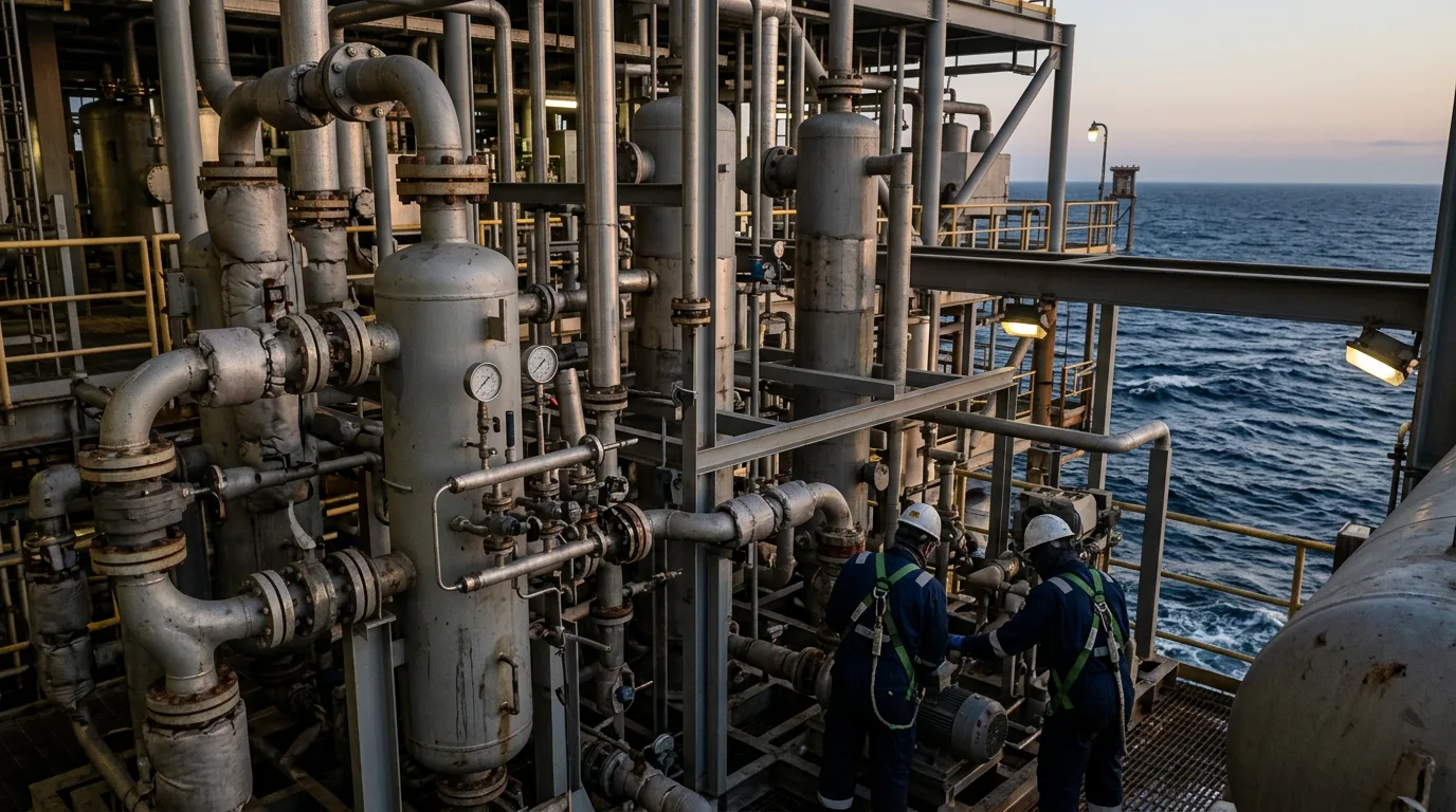
Floating gas units are limited by deck area, weight, and a process that must keep working while the hull moves. A gravity separator sized for a land plant can lose its performance on a moving vessel because the liquid surface sloshes, level instruments become noisy, and the gas–liquid interface is no longer where the design assumed. Add a slug arriving from a long riser or tieback and the first vessel on the deck becomes the unit that decides whether compressors, dehydration, and export stay online. A trip here usually costs production, and a liquid carry-over into a compressor suction scrubber can cause mechanical damage. This article covers motion effects on separation, compact technology selection, and slug-catcher sizing logic for floating gas developments.
Standards and requirements context
The standards below set the framework, but none gives a ready-made answer for motion-affected separation. Treat them as boundaries and fill the gaps with project-specific analysis.
API 12J(Specification for Oil and Gas Separators) covers design and fabrication of separators. It is written for fixed installations, so motion allowances must be added by the project.API 521(Pressure-relieving and Depressuring Systems) governs relief and blowdown sizing. Slug-driven liquid arrival at a flare or vent header is a scenario to check against it.IEC 61511(functional safety for the process industry) governs high-level and high-high-level protection functions on separators and slug catchers. The motion-induced level noise discussed below directly affects how these functions are designed and proof-tested.ISO 13702(control and mitigation of fires and explosions on offshore production installations) bears on how much hydrocarbon inventory sits in a congested deck layout. This is a direct reason to keep slug-catcher volume as small as the flow assurance allows.
Motion effects on separator performance
What actually degrades
A floating unit imposes roll, pitch, and heave. The process consequences fall into four groups:
- Liquid sloshing. In a horizontal vessel, free liquid surface moves along the vessel axis or across it, depending on orientation relative to the dominant motion. Sloshing disturbs the settling zone, re-entrains liquid into the gas, and can uncover outlet nozzles.
- Level measurement error. Differential-pressure and displacer instruments see moving liquid as a fluctuating level. Filtering to suppress the noise delays the response to a real slug, which is the wrong trade-off for a slug-catcher.
- Effective residence time. Tilt shortens the effective liquid path and changes the interface geometry. The nominal retention time on the datasheet is not what the fluid experiences.
- Demister performance. Mesh and vane demisters depend on defined gas velocity and drainage paths. Motion disturbs drainage and can allow re-entrainment even at design gas load.
Design responses
- Favour vertical or low-aspect-ratio geometry where liquid residence requirements allow. A smaller free surface moves less liquid than a long horizontal drum.
- Orient horizontal vessels deliberately against the dominant motion axis, and confirm the choice with the marine design team rather than relying on a default.
- Add internal baffling (perforated or wave-breaker plates) to damp sloshing, and keep nozzle locations clear of the zones where liquid is thrown.
- Use level instruments suited to motion, such as multiple measurement points or radar and DP combinations. Set the level philosophy so that the protective function is not tuned around nuisance noise.
- Specify the motion envelope in the datasheet. The vessel vendor needs the design motion criteria and acceleration cases, not just flow and pressure.
The process design must also be consistent with the sea-state criteria applied to the hull. A separator that works in the design case but loses control in an intermediate sea state will cause more operating pain than an extreme-case trip.
Compact separation technology for tight deck space
The savings come from lower steel weight, smaller footprint, and less inventory. The same source frames compact processing as a growing trend, which means vendors are now offering many options, and selection needs discipline.
Comparison of options
| Technology | Where it fits | Motion sensitivity | Main limitation |
|---|---|---|---|
| Conventional horizontal gravity separator | Bulk liquid removal where space permits | High (free surface) | Footprint and weight |
| Vertical scrubber with vane or mesh demister | Gas polishing upstream of compression | Moderate | Gas-velocity window; drainage |
| Inline cyclonic degasser or gas–liquid cylindrical cyclone | Bulk gas–liquid split, slug mitigation at the inlet | Low (momentum-driven, small free surface) | Narrow turndown; needs a downstream liquid-handling vessel |
| Multi-cyclone or axial cyclone internals in a vessel | High gas throughput in small diameter | Low to moderate | Pressure drop; sensitive to liquid loading and solids |
| Finger or pipe-type slug catcher | Large slug volumes where deck length exists | Moderate (stratified flow in long pipes) | Weight, footprint, support structure on a moving hull |
Evidence from a field case
PRODUCTION TECHNOLOGY: Compact in-line separation solves severe slugging problems on Statfjord B (Offshore Magazine, 2001) describes an inline degasser, an 18-in. unit, applied to severe slugging on a floating-type platform arrangement. The lesson is that moving the first gas–liquid split into the pipe, where momentum separation dominates, can reduce the slug amplitude seen by the downstream vessels. It does not eliminate the need for a liquid-handling volume, but it can shrink it.
Selection logic
- Use a compact inline or cyclonic stage for the first split, so the downstream drum receives a calmer, more predictable stream.
- Keep a conventional or semi-compact vessel where operational stability, solids tolerance, or turndown matter more than weight.
- Treat solids early. The paper Filtration of Gas on Offshore Platforms With Special Reference to Sand Removal and Slug Catching (SPE) links sand removal and slug catching as one design problem, and cyclone internals are less forgiving of erosion and plugging than open gravity vessels.
- Confirm that fuel-gas and utility gas conditioning is not forgotten.
Slug-catcher sizing for floating gas
Know the slug source
The design volume depends on where the slugs come from:
- Hydrodynamic slugging in long multiphase lines.
- Terrain- or riser-induced slugging, including severe slugging at the riser base.
- Pigging slugs, usually the largest controllable event.
- Ramp-up slugs after a shutdown or rate change, as liquid accumulated in low points is swept out.
It is a land-based reference, so its volume logic transfers, but the motion-related adjustments described above do not come from it.
Sizing logic
A slug catcher must hold the liquid surge while the downstream system drains it at a controlled rate. The governing balance is:
V_required ≥ (Q_in,slug − Q_drain) × t_slug + V_margin
where Q_in,slug is the liquid arrival rate during the slug, Q_drain is the controlled liquid outflow, t_slug is the slug duration, and V_margin covers level-instrument uncertainty and motion allowance. Inputs come from transient multiphase simulation, not hand estimation. V_margin should be explicit, because on a floater it has to cover the part of the vessel that cannot be used reliably when the liquid surface is moving.
Reducing the catcher volume
Increasing Q_drain, the downstream liquid-handling rate, is often cheaper in deck terms than increasing V_required, so it is worth checking first:
- Size the condensate or liquid pumps, stabilisation train, and downstream separators for slug-drain flow, not only for steady-state flow.
- Use choke or inlet-valve control driven by early slug detection to flatten the arrival profile.
- Control pigging frequency and ramp-up rates, so the biggest slugs are the planned ones.
A smaller catcher also means less hydrocarbon inventory on deck, which supports the fire and explosion strategy under ISO 13702.
Illustrative scenario
This scenario is illustrative and is not drawn from a specific project.
A floating gas unit receives wet gas through a flexible riser from a long subsea tieback. The topsides concept is a vertical inlet scrubber feeding compression. The first design review finds that a routine pigging run would deliver a liquid slug larger than the scrubber's liquid section can hold. The options reviewed are:
- Enlarge the scrubber. This adds weight high on the hull and increases the sloshing mass.
- Add a finger-type catcher. This costs deck length the layout does not have.
- Install an inline cyclonic degasser at the riser arrival, with a modest liquid-handling vessel behind it, and increase the condensate pump capacity so the drain rate is higher during the pigging event.
The team chooses option 3 and writes a pigging procedure that controls the pig speed and stages the liquid drain. The sizing equation above is then re-run with the revised Q_drain, and the transient simulation is repeated with a motion allowance in V_margin. The result is a smaller vessel than option 1, validated against the controlled-pigging case. The review also notes that the level-protection function must be specified for a moving vessel, with IEC 61511 proof-test and response-time assumptions confirmed against the filtered level signal.
Opening the pig receiver afterwards is a hydrocarbon-containing-equipment task. It requires isolation, depressurisation, verification of zero energy, LOTO, hazardous-area precautions, continuous gas detection, and safe venting to the designated system before any closure is opened.
Decision checklist
- Has the project issued a motion envelope (roll, pitch, heave, accelerations) to every separator and scrubber vendor?
- Is each horizontal vessel oriented deliberately relative to the dominant motion, with the reasoning documented?
- Does the level-measurement design keep real-slug response time acceptable after filtering, and has the protective function been specified against
IEC 61511? - Does each demister selection account for drainage under motion, not only gas load?
- Has the slug source been identified (hydrodynamic, terrain, severe, pigging, ramp-up), and has the largest controllable event been defined?
- Is the downstream drain rate sized for slug conditions, not only steady-state?
- Is V_margin stated explicitly and justified for motion?
- Have solids loading and sand removal been considered before selecting cyclone internals?
- Is fuel-gas conditioning protected against slugs, solids, and aerosols?
- Has liquid arrival at the flare and vent headers been checked under
API 521? - Does the inventory in the slug-handling system fit the fire and explosion strategy under
ISO 13702? - Is the pig receiver procedure written with full isolation, depressurisation, zero-energy verification, LOTO, gas detection, and venting steps?
Conclusion
On a floating gas unit, separation performance is set by how the vessel behaves in motion, and slug-catcher volume is a trade between deck space and downstream drain capacity. Start by defining the slug cases and the motion envelope, then test whether a compact inline first stage and a higher drain rate can replace a large catcher. Before committing to a vendor, run a transient multiphase simulation with explicit motion allowances. Then review the level-protection design against IEC 61511 with the marine, process, and safety teams together.