Why expansion projects expose hidden integrity gaps
Few subsea pipeline expansions start from a clean sheet. A new tie-in, higher throughput, a change in fluid composition or a life extension asks a line to do work it was never designed for. The existing asset carries corrosion, free-span changes, seabed movement and a weld history nobody fully remembers. The new section brings its own materials, installation loads and operating envelope. Most of the unresolved risk sits at the interface between the two.
The cost shows up in three ways. A re-qualification study can find that the original design basis no longer covers the new duty, and then the operator pays for late retrofits such as span rectification, extra corrosion protection or a derated envelope. Or the expansion goes ahead on stale data, and the first sign of trouble is an in-line inspection (ILI) finding or a shutdown. Early design decisions set long-term integrity. A Lloyd's Register study for the Norwegian Ocean Industry Authority (Havtil) found that early design choices and robust qualification of subsea connectors can materially shape the long-term integrity of subsea pipelines (LR, 2026).
This article covers the structural and metallurgical questions that matter most when scaling up existing subsea infrastructure, and how to organise the evidence before committing to a design.
Standards and requirements context
Three documents frame most expansion work.
- DNV-ST-F101 Submarine pipeline systems (edition 2021-08, amended 2021-12) gives an internationally acceptable framework for submarine pipeline systems in all lifetime phases, with a focus on structural assessment (DNV, 2021). For an expansion, use it as the reference for limit-state checks on new sections and as the design basis against which modified operating conditions are judged.
- DNV-RP-F116 Integrity management of submarine pipeline systems (December 2021) covers integrity management across the operating life. It is the natural anchor for deciding what inspection, monitoring and assessment the combined old-and-new system needs (DNV, 2021).
- LR-RP-002 Recommended Practice for Subsea Pipelines (Lloyd's Register, 1 July 2023) is a further recommended practice for subsea pipeline design and operation. It is useful where a Lloyd's Register-classed or verified scope is involved (LR, 2023).
Havtil's guideline to subsea integrity management adds a useful process point. In detail design, the concept definition needs refining and suitable operating envelopes need establishing. That is exactly what an expansion disturbs.
Defect assessment of corroded or damaged sections, fracture assessment and sour-service material qualification each have their own applicable standards. Name the edition in the project's design basis and confirm it. Don't work from memory.
Structural challenges
Re-establishing the design basis
The first job is deciding which parts of the original design basis still hold. Throughput, pressure, temperature, water cut and fluid chemistry all shift the load cases. The expansion can also change the installation and operating sequence. A line designed around one start-up and shut-in philosophy may see far more transients under the new duty.
Re-derive these inputs from current data, not from the original design report:
- Maximum and minimum operating pressure and temperature, including shut-in and transient conditions.
- Actual wall thickness and ovality, based on the latest ILI and survey data.
- Seabed conditions and as-found pipeline position, which often differ from the as-laid drawings.
- Remaining life of coatings and cathodic protection.
Wall thickness, collapse and thicker pipe
Going into deeper water or higher pressure pushes designs toward heavier walls. The EPRG position paper "Deeper, Longer and Thicker: Challenges for the Design of Subsea Pipelines" (Selker et al., 2022) frames this trend directly. Thicker walls bring their own problems: collapse resistance, fabrication tolerances, weld procedure qualification and how heavy-wall material behaves under installation strain. The wall that satisfies hoop stress is not always the wall that satisfies external-pressure collapse or local buckling under combined loading. Where the new section is thicker than the host line, the transition also changes stiffness and weld geometry.
Global buckling, walking and expansion loads
Higher operating temperature and pressure raise the effective axial force. Lines that were stable can start to buckle laterally or walk along the seabed. Terminations, spools and tie-in structures soak up the cumulative displacement. Check these in the analysis:
- Feed-in of the new section's thermal expansion into existing end structures.
- Whether the original route has intentional buckle initiators or relies on seabed friction.
- Whether earlier movement has already used up the design allowance.
Free spans and seabed change
Spans move over time with scour, sand wave migration and previous interventions. A span that was fine at the original flow condition may now be vulnerable to vortex-induced vibration at a higher flow rate or with a different fluid density. Refresh the survey and re-run the span assessment against the new operating envelope. Don't carry the old span list forward.
Connectors and interfaces
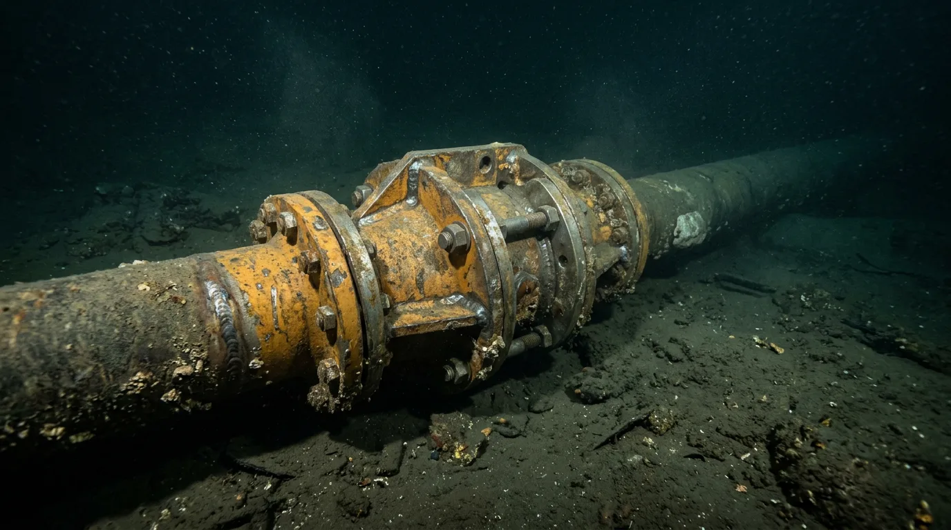
Tie-ins, mechanical connectors and flange or spool interfaces concentrate both structural and metallurgical risk. The LR/Havtil work singles out qualification of subsea connectors as a driver of long-term integrity (LR, 2026). Treat the connector as a system that includes seals, bolting, coating and cathodic protection continuity. Qualify it against the new loads, not just the catalogue rating.
Metallurgical challenges
Material compatibility between old and new
Joining new line pipe to a decades-old host brings differences in grade, chemistry, toughness and manufacturing route. Specific concerns:
- Weldability and heat-affected zone (HAZ) toughness. Confirm that welding procedures are qualified on the actual host material, not just the new pipe. Host chemistry may be unknown or inconsistent, so get material verification before procedure qualification.
- Strength mismatch. Under-matched or over-matched welds shift strain localisation, especially under strain-based loading from buckling or reeling.
- Fracture toughness at low temperature. Depressurisation can cool the line significantly. Confirm that toughness stays adequate across the full operating and shutdown envelope.
Corrosion mechanisms under a changed fluid
A change in produced fluid can switch the dominant corrosion mechanism. More water cut, higher CO₂ or H₂S partial pressure, or changed inhibitor compatibility can invalidate the original corrosion allowance. Where H₂S rises, sour-service qualification of both parent material and welds becomes a gate item. Corrosion-resistant alloy (CRA) clad or lined solutions need attention to weld overlay quality, dilution and the integrity of the CRA layer at field joints.
Cathodic protection and hydrogen effects
Expanding the system adds anode demand and may change current distribution. Under cathodic protection, high-strength steels and some weld zones can crack from hydrogen, so the protection design has to balance adequate polarisation against over-protection. Verify that anode capacity covers the combined system and that electrical continuity at the tie-in is as intended.
Fatigue
Cyclic loading at free spans, risers and tie-ins is usually governed by weld quality and geometry. Under the new duty, fatigue accumulation on the old section starts from a damage state that is often poorly documented. Use the inspection history to work out how much damage can reasonably be assumed to have built up.
Comparing expansion scenarios
| Expansion change | Main structural concern | Main metallurgical concern | Evidence to obtain first |
|---|---|---|---|
| Higher throughput | Free-span vibration, flow-induced loads | Erosion and erosion-corrosion at bends and tie-ins | Current span survey, flow assessment |
| Higher pressure or temperature | Effective axial force, buckling, walking | Elevated-temperature properties, coating limits | Updated thermal and global buckling analysis |
| Fluid chemistry change | Limited direct effect | Sour service, CO₂ corrosion, inhibitor performance | Fluid sampling, corrosion model update |
| New tie-in or branch | Interface stiffness, spool loads | Dissimilar material welding, CP continuity | Host material verification, weld procedure qualification |
| Life extension | Cumulative fatigue and span change | Corrosion growth, coating and anode depletion | ILI data, CP survey, defect assessment |
Illustrative scenario
The following scenario is illustrative and does not describe a real project.
An operator plans to tie a new subsea field into an older export line. The new field's fluid carries more water and a higher acid-gas content than the original. The new flowline is thicker-walled and a higher grade than the host. The operator initially plans to rely on the original design report and a limited tie-in analysis.
A structured review changes the plan:
- Data refresh. The latest ILI run shows localised wall loss near an earlier span. A new survey shows that scour has altered several spans.
- Design basis re-derivation. The updated fluid case changes the corrosion model. The previous corrosion allowance and inhibition strategy no longer cover the duty without further assessment.
- Interface assessment. The thicker, higher-grade new spool joins a host section of unknown chemistry. Material verification is required before weld procedure qualification, and the strength mismatch is checked for strain localisation.
- Global analysis. The new thermal duty is run through a global buckling and walking analysis, including the displacement history of the existing end structure.
- Outcome. The study results in a revised operating envelope, a targeted span intervention, a changed inhibition and monitoring plan and a qualified connector with a CP continuity check. Each item is cheaper to fix before the tie-in than after.
Any tie-in work that breaches hydrocarbon-containing pipework must be planned with positive isolation, depressurisation, verification of zero energy, lock-out/tag-out, hazardous-area precautions, gas detection and safe venting or flaring arrangements before intervention starts.
Checklist and decision guidance
Use these items as a gate review before design freeze.
- Confirm that the design basis is rebuilt from current data, not from the original design report.
- Obtain recent ILI and survey results and reconcile them with as-laid drawings.
- Verify host-pipe material properties (grade, chemistry, toughness) at the tie-in location before qualifying welding procedures.
- Re-run global buckling, walking and free-span analyses with the new operating envelope and as-found seabed.
- Re-assess the corrosion mechanism for the new fluid, including sour-service requirements where acid-gas content rises.
- Check cathodic protection capacity and continuity for the combined system.
- Qualify connectors against the new loads, including seals, bolting and coatings.
- Evaluate fatigue on the existing section starting from an honest estimate of accumulated damage.
- Define the integrity management plan for the combined system, using DNV-RP-F116 as the framework, and set inspection baselines before start-up.
- Record the assumptions that lack data and assign an owner and a closing date for each.
Decision guidance: if host-material data is incomplete, treat the tie-in as a high-uncertainty interface and defer weld procedure qualification until verification is complete. If the fluid change moves the corrosion mechanism, don't carry the old corrosion allowance forward without a documented reassessment. If global analysis shows the line consuming remaining displacement allowance, change the design or the envelope rather than accepting reduced margin.
Conclusion
Expansion integrity depends less on any single calculation than on whether the combined system is assessed on current evidence. Rebuild the design basis from recent data, treat connectors and old-to-new interfaces as qualified systems, and re-check structural and metallurgical assumptions against the new fluid and operating envelope.
As next steps, run a gap review of the original design basis against the proposed duty, commission material verification and an updated survey before detailed design freezes, and align the post-expansion integrity management plan with DNV-RP-F116 so inspection baselines exist from day one.