Boil-off gas (BOG) is a managed flow on an LNG carrier, sized for one particular heat-ingress condition. After a hull damage incident, that condition may no longer hold. Impact, grounding, collision or fire exposure can degrade insulation, flood adjacent spaces or create local cold spots. Heat ingress climbs while gas-burning and reliquefaction capacity stays where it was. If generation outruns disposal, tank pressure rises. That leaves three choices: accept the rise, burn gas in the gas combustion unit (GCU), or vent. Each carries safety, commercial and environmental consequences. The same event can also leave the ship idle or slow-steaming while the cargo keeps boiling. That is the exposure Steamship Mutual describes for congestion and standby conditions in its risk alert on excessive BOG exposure.
This article covers how to think about BOG management when containment may be compromised, and how to sequence insulation integrity checks without creating a second hazard.
Standards and requirements context
The design basis for LNG carriers is the IMO IGC Code (International Code for the Construction and Equipment of Ships Carrying Liquefied Gases in Bulk), applied through SOLAS and class rules. It sets expectations for containment, secondary barriers, hull steel temperature protection, pressure and vacuum relief, and gas detection. Class societies enforce these through survey regimes.
Three technical references matter most here:
- LNG Operational Practice (2nd Edition, 2020) states the core mechanism. If insulation efficiency deteriorates for any reason, the inner hull steel temperature may fall, creating a cold spot and increasing boil-off from the affected tank. If the increase exceeds the capability of the cargo handling system, excess gas may be vented. It is the right starting point for thermal-damage scenarios. Degraded insulation changes the heat input that the relief system must handle, so the two cannot be assessed independently.
Operators should also check how emissions accounting treats surplus BOG.
How BOG behaves when insulation is compromised
The baseline: a designed balance
In normal service, heat leaks through the insulation at a rate the designer expected. The resulting vapour feeds the propulsion plant (dual-fuel engines, boilers or gas injection engines), goes back to liquid in a reliquefaction plant where one is fitted, or ends up in the GCU.
A prolonged post-incident delay therefore affects cargo quality at delivery as well as pressure.
The damaged case: the heat input changes
To a first approximation, the BOG generation rate follows an energy balance:
ṁ_BOG ≈ Q̇_total / λ where Q̇_total is the heat ingress rate (power, in W), λ is the latent heat of vaporisation (J/kg), and ṁ_BOG is the boil-off mass flow rate (kg/s).
where ṁ_BOG is the boil-off mass flow, Q_total is the total heat ingress into the cargo (insulation leakage plus any additional sources such as pump work or sloshing energy), and λ is the latent heat of vaporisation of the cargo. Hull damage can raise Q_total in several ways:
- Compressed, displaced or wetted insulation panels.
- Loss of nitrogen integrity in insulation spaces, letting moisture or air in.
- Flooded ballast or void spaces that put a different thermal boundary against the inner hull.
- Fire or heat exposure that damages insulation material.
- Structural distortion that changes the contact between insulation and the tank structure.
Sloshing is a separate concern. An impact followed by a heavy-weather transit loads a possibly weakened system with both stresses at once.
Why the cold spot matters
The inner hull is ordinary ship structural steel, not cryogenic-grade material. When insulation fails locally, the steel behind it cools, and the hazard is brittle behaviour of hull steel. The extra BOG is the more visible symptom. A hull temperature trend that diverges from its neighbours is the earlier warning. Treat it as a structural safety issue first and a BOG issue second.
BOG disposal options after damage
| Option | What it does | Constraint after damage | Decision consideration |
|---|---|---|---|
| Burn in propulsion or power plant | Converts BOG to useful work | Limited by engine or boiler demand; a slow or stopped ship burns less | Effective only if the ship is making way and the plant is available |
| Reliquefaction (where fitted) | Returns liquid to tanks | Limited by plant capacity and machinery condition; many ships do not have it | Check whether damage affects machinery spaces, power or cooling water |
| Gas combustion unit | Destroys surplus gas without a vent | Capacity is finite; the energy is wasted and emissions are generated | Preferred over venting, but its capacity must be confirmed, not assumed |
| Tank pressure accumulation | Absorbs gas by letting pressure rise | Bounded by tank design pressure and relief settings | A short-term buffer; the rate of rise must be trended against remaining margin |
| Controlled venting to mast | Releases gas to atmosphere | Last resort; hazardous-area, environmental and regulatory implications | Needs a documented decision, weather and dispersion assessment, and notification as required |
Pressure accumulation is the option people most often misjudge. It helps, but the margin to relief set pressure is the only buffer, and a tank with damaged insulation eats through it faster than the others. Trend each tank on its own. Aggregated plant data can hide a single tank that is going bad.
Insulation integrity inspection after an incident
Sequence matters
- Stabilise first. Confirm structural and fire safety, watertight integrity and stability. Contain any cargo release before looking at insulation.
- Use remote data. Insulation space gas detection, nitrogen consumption trends, hull and tank temperature sensors and tank pressure trends all tell you something without opening anything. Compare each against the pre-incident baseline for the same tank and loading condition.
- Establish the boundary of concern. Map the damage location against tank and insulation space boundaries. Prioritise tanks next to the impact or heat source.
- Engage class and flag early. Surveyors will want evidence of containment integrity before the vessel resumes normal cargo operations. Bring in the cargo containment system designer or licensor where the damage touches the insulation structure.
- Plan physical inspection. Move to entry or intrusive inspection only when remote data cannot answer the question.
Interpreting the indicators
- Rising nitrogen make-up in an insulation space suggests a leak path to atmosphere or to the adjacent space.
- Gas detection in an insulation space indicates primary barrier leakage or contamination from outside. Treat it as a cargo containment event until proven otherwise.
- A localised drop in hull temperature against neighbouring sensors points to a thermal short. A uniform shift across sensors is more likely to reflect cargo or ambient conditions.
- Higher BOG with no machinery explanation fits increased heat ingress, but confirm the measurement chain (flow, composition, tank level) is reliable before concluding anything.
Safe inspection of insulation, void and hold spaces
Any inspection that opens, depressurises or enters a space next to hydrocarbon-containing equipment needs a controlled permit-to-work process:
- Isolation: positively isolate the space from cargo, vapour and inert gas lines, with valve positions verified and tagged.
- Depressurisation: reduce pressure in the space through the designed route, not by improvised venting.
- Verification of zero energy: confirm by gauge and by test that there is no residual pressure, stored energy or flow path.
- LOTO: lock out and tag isolation points and any associated machinery, with a named owner for each lock.
- Hazardous-area precautions: use certified equipment only, control ignition sources, and apply bonding and static controls.
- Gas detection: test for hydrocarbon, oxygen and toxic gases before entry and continuously during work, using calibrated instruments.
- Safe venting: route any purged or displaced vapour to the designated safe location, accounting for wind and nearby personnel.
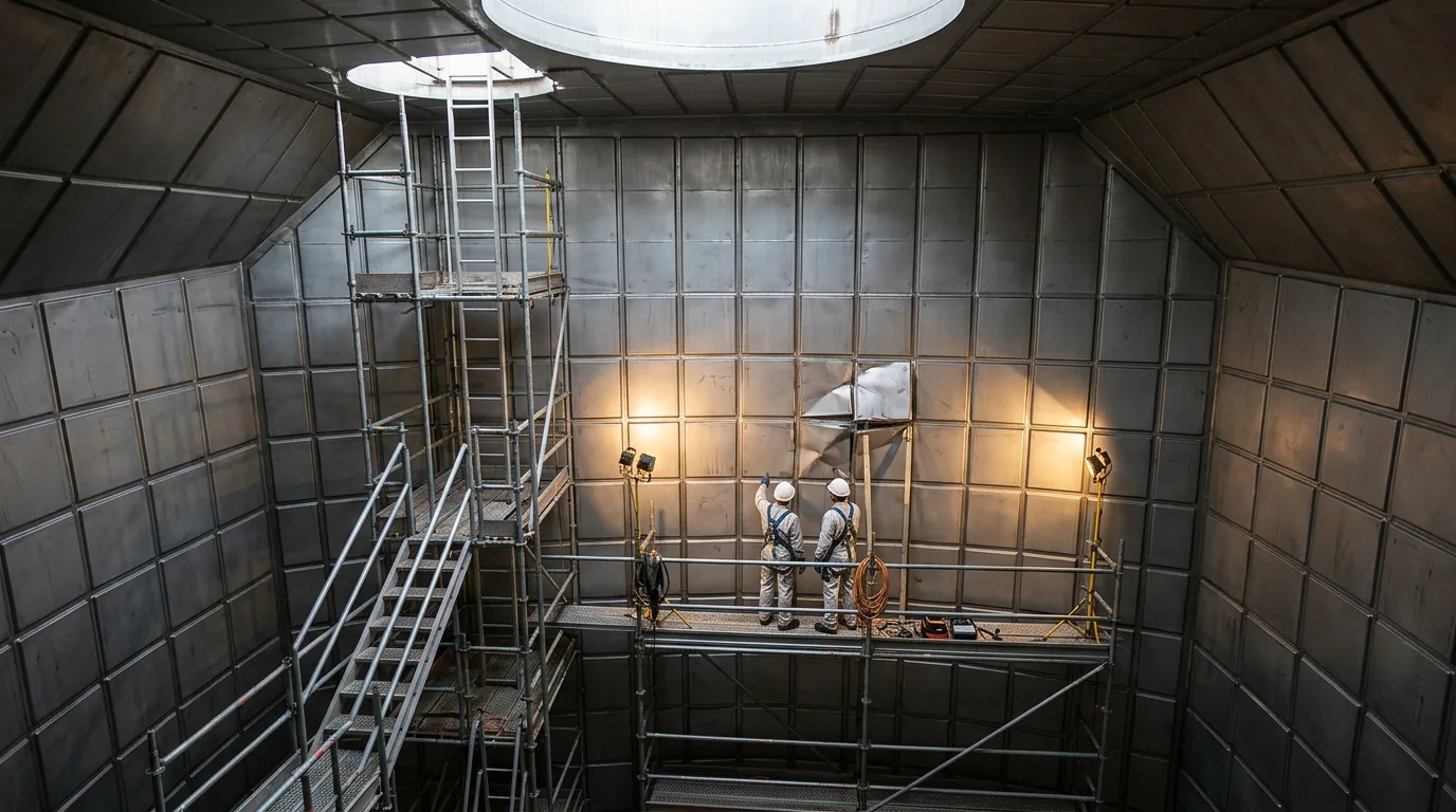
Enclosed space entry rules apply on top of all this. A cold, damaged insulation space can combine oxygen deficiency from nitrogen, flammable gas and structural instability in one place.
Illustrative scenario
This scenario is constructed for guidance and is not a reported event.
A laden carrier takes a side impact near a ballast tank adjacent to one cargo tank. There is no visible cargo release. Over the following period the duty officer sees three changes:
- Tank pressure in one tank rises faster than in the other tanks.
- Nitrogen make-up to that tank's insulation space increases.
- One hull temperature sensor in the impact zone reads progressively colder than its neighbours.
Reasoning through it:
- The three signals agree with one another, which makes a measurement fault less likely. They point to local insulation degradation in that tank.
- From ṁ_BOG ≈ Q_total / λ, a higher Q_total in one tank raises its boil-off. Total disposal capacity (engines plus GCU) now has to be compared against the new total generation. If the ship is slow or stopped, engine consumption falls just as generation rises.
- The cold-spot trend takes priority because it bears on hull steel integrity. The master consults class and the containment designer about acceptable operating conditions for that tank.
- Cargo operations options include lowering the tank's pressure through the tank-specific gas handling route, discharging or transferring that tank's cargo first if discharge is feasible, and arranging intrusive inspection once the vessel is in a safe location. Venting is documented as a last resort, with its trigger criteria agreed in advance.
- The commercial team hears about it early, because delay and cargo condition at delivery will affect the terminal.
No numerical sizing is given because the heat-ingress and plant-capacity data are ship specific.
Practical checklist
- Record a pre-incident baseline for each tank: pressure trend, BOG flow, insulation space nitrogen use and hull temperatures.
- Trend each tank individually after the event, not just the plant total.
- Confirm the actual, current capacity of every disposal route (engines, reliquefaction, GCU) given machinery condition and ship speed.
- Compare hull temperature sensors against their neighbours and investigate any local divergence as a structural concern.
- Treat any hydrocarbon in an insulation space as a possible containment breach.
- Check sensor and flow-meter reliability before drawing conclusions from them.
- Define venting criteria, authority and notification steps before they are needed.
- Notify class, flag, insurers and the cargo owner or terminal early, with data.
- Consult the containment system designer on insulation damage that is not visible from remote data.
- Control all entries and intrusive work under permit with isolation, depressurisation, zero-energy verification, LOTO, gas detection and safe venting.
- Consider cargo ageing and delivery specification if delay is prolonged.
Conclusion
After hull damage, the key question is whether the heat ingress assumption behind the ship's BOG plan still holds. Answer it with trended, tank-by-tank data before anyone opens a space. Treat a cold-spot trend as a structural risk, keep venting as a documented last resort, and bring class and the containment designer in early.
As a next step, check whether your vessels' baseline data (per-tank pressure, nitrogen consumption, hull temperatures) are recorded in a form that allows a quick before-and-after comparison. Then rehearse the post-incident decision sequence in the cargo operations manual, including who authorises venting and how the commercial side is informed.