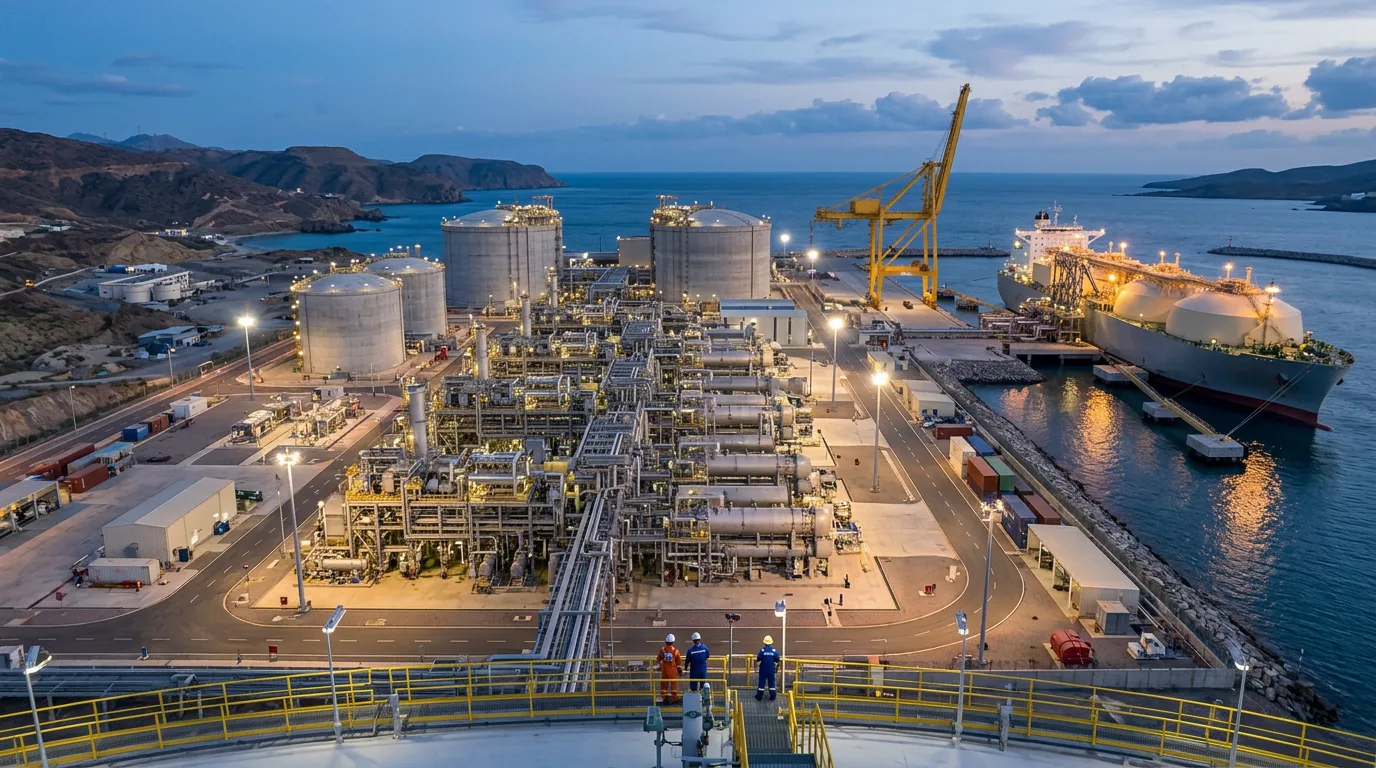
Liquefaction capacity at a constrained port site is seldom set by the cold box nameplate. Something else binds first: plot area for the next train, the hazard distances around it, cooling duty on a hot day, or the number of ships the berth can load in a month. If the train is sized or arranged without looking at those limits, the plant gets a design rate it cannot hold. Feed gas gets curtailed, cargo windows get missed, or a costly brownfield expansion becomes necessary to recover rate that better integration would have delivered. For a midstream planner the real question is not "how big a train fits?" It is "which arrangement of train, storage, and marine facilities turns the most gas into loaded cargoes per year on this footprint?"
Standards and Requirements Context
The design basis for an onshore LNG plant in a port environment rests on a small set of documents:
EN 1473covers the design of onshore LNG installations. It sets out spacing, hazard assessment, and the safety philosophy that decide how tightly equipment can be packed.NFPA 59Ais the standard for the production, storage, and handling of LNG. It governs siting, spill containment, and separation distances. These often drive plot layout more than process considerations do.API 617covers axial and centrifugal compressors and expander-compressors. It applies to the refrigerant compressor trains that dominate train footprint and power demand.API 521covers pressure-relieving and depressuring systems. Flare and relief capacity limits how much equipment can fit into a restricted area.IEC 61511covers functional safety for safety instrumented systems in the process industry. Any optimizer that pushes the train toward its limits has to sit above the independent protection layers designed to this standard, never inside them.- The
IEC 60079series governs equipment in explosive atmospheres. Dense layouts create more classified area interfaces to manage.
Local port authority rules, marine pilotage requirements, and jurisdictional LNG regulations apply on top of these. Confirm them site by site.
Where the Footprint Actually Binds
In a port setting, constraints fall into four groups. Each one limits throughput in its own way.
- Land side. Plot area for liquefaction, pretreatment, utilities, tanks, and flare, plus the separation distances the siting standards require.
- Marine side. Berth count, jetty loading arm capacity, turning basin, tidal windows, and pilotage rules.
- Utilities. Cooling medium availability, power supply, and the ability to export or flare.
- Interfaces. Pipeline entry, truck or rail loading if present, and neighbouring port activity.
The MDPI review of natural gas liquefaction design and optimization makes the same argument for offshore plants. FLNG has to cope with very limited space, more complex operating environments, and variable feed composition. A congested onshore port site shares the first and third problems even if it avoids the second. Compact, robust process choices developed for FLNG are therefore a useful reference for port-constrained onshore projects.
Train Architecture Under Space Constraints
Process Cycle Selection
The liquefaction cycle trades thermodynamic efficiency against equipment count, plot area, and operability. The table below is a qualitative screening guide. It does not replace a licensor comparison.
| Consideration | Nitrogen expander cycle | Single mixed refrigerant | Dual mixed refrigerant or cascade |
|---|---|---|---|
| Equipment count and plot demand | Low | Moderate | Higher |
| Specific power for a given rate | Highest | Intermediate | Lowest |
| Hydrocarbon refrigerant inventory | None | Present | Present |
| Sensitivity to feed composition change | Low | Moderate | Moderate to high |
| Suitability for tight hazard-distance sites | Favourable | Depends on layout | Needs more area and spacing |
| Fit for large single-train throughput | Limited | Good | Strong |
Nitrogen cycles can win where hazard distances, not power cost, dominate the site. Mixed-refrigerant cycles win where gas is the scarce resource and the plot can take a larger machinery train. If the plot is really small and the rate target is high, test a hybrid: a more efficient cycle for base load, with a compact unit for incremental capacity.
One Large Train, Several Smaller Trains, or Modules
- Single large train. Best footprint per unit of capacity. The whole plant, though, depends on one set of compressors, and turndown is limited by the machine envelope.
- Multiple trains. Better availability and staged commissioning. They need more piping, utility connections, and control rooms, and each train brings its own spacing penalty.
- Modular or skidded trains. Shorter construction time on a congested site and less laydown, since fabrication moves off-site. Heavy-lift routes and marine delivery then become the critical-path items.
On a port with a restricted laydown area and an active marine environment, the construction method can matter as much as the process cycle.
Cooling Medium and Ambient Sensitivity
Refrigerant compressor drivers lose available power as inlet air warms. That is why LNG output usually tracks ambient conditions, and why a train that hits target on a cool day can come up short in summer. Air-cooled exchangers avoid a water intake, but they eat plot area and make the plant more sensitive to ambient temperature. Seawater cooling shrinks the footprint and flattens the seasonal swing, but it needs intake and outfall works and environmental permits. In a port, those marine works may already exist, or existing traffic may block them. Bring the harbour authority in early.
Design the driver and cooling system against the hottest credible operating period, not the annual average. Otherwise the shortfall is built in from day one and only shows up in operation.
Operating the Train Closer to Its True Limits
Advanced Process Control and Production Optimization
Once the equipment is built, throughput becomes a control problem. The TREA patent application on production optimization describes a method for optimizing a natural gas liquefaction process by selecting at least one manipulated variable (MV) to control the process. The core of the approach is deciding which handles the optimizer may move and which constraints it must respect.
In practice, the MVs on a mixed-refrigerant train usually include refrigerant compressor speed or load, refrigerant composition and inventory adjustments, and expansion valve positions. The constraints are compressor surge and power limits, exchanger temperature approach and rate-of-change limits, and product specification. The optimizer should push the train against whichever constraint is binding right now. That constraint shifts with ambient temperature and feed composition, so a fixed operating point leaves capacity on the table for much of the year.
Three guidelines follow:
- Keep the optimizer in the control layer. Safety functions designed to
IEC 61511must stay independent and must not be bypassed or retuned by the optimizer. - Identify the binding constraint before buying more control. If the real limit is marine, optimizing the cold box gains nothing.
- Validate any optimizer move against the compressor maps and the vendor's operating envelope under the applicable
API 617machine data.
Debottlenecking an Operating Train
The Freeport LNG debottlenecking presentation at Gastech, co-authored by Freeport LNG and Kiewit staff, shows how an operator and an EPC contractor work through capacity increases on an existing facility. The logic matches general practice: find the constraint, remove it, then find the next one. On a congested site, test every proposed fix against the plot, the relief and flare capacity (API 521), and the siting rules in NFPA 59A and EN 1473 before it goes into the schedule.
Any tie-in or modification that opens hydrocarbon-containing equipment needs the full control sequence: positive isolation, depressurisation to a safe location, verification of zero energy, lockout/tagout, hazardous-area precautions and permits, continuous gas detection, and safe venting or flaring of inventory. On a tight site, adjacent live equipment makes this harder, not easier.
The Port Interface Often Sets the Real Ceiling
A liquefaction train feeds storage, and storage feeds ships. Annual deliverable volume can be written as:
Q_deliverable = min(Q_liquefaction, Q_storage-and-rundown, Q_berth-and-loading)
All three terms are expressed in the same units (volume or energy per year). Raising the first term only raises output if it is the smallest one. Several sources in this area show that terminal capacity is often governed by operations rather than hardware.
- The Liuheng LNG Terminal study uses simulation to evaluate terminal capacity. It treats the terminal as an interacting system of vessel arrivals, berths, and storage, not as a set of independent nameplate values.
- The PolyU study (2025) on ship traffic scheduling in LNG ports includes navigation characteristics and night sailing risks in its model. Channel rules and visibility restrictions determine how many cargo windows are really available.
- The Jefferson Rail Terminal project by HPC Hamburg Port Consulting concerns a rail terminal, not LNG. It dealt with infrastructure nearing its limit by simulating operational procedures, which makes it a useful analogy for finding capacity without new construction.
- This is not an LNG case, but it supports the principle that operating method can release capacity where land cannot be added.
The common lesson is to build a discrete-event model of the whole chain, from feed gas to departing ship, before fixing train size.
Illustrative Scenario
This scenario is illustrative and not from a listed source. A port-adjacent site has room for one train, one storage tank, and a single berth. The initial plan is the largest single mixed-refrigerant train that fits.
A system model that includes ship arrivals, tidal and night-sailing restrictions, and tank buffer shows that, in the worst seasons, loading windows rather than liquefaction limit annual output. The train sits idle waiting for tank space while ships wait for the tide. The planners respond in this order:
- Add storage buffer or revise tank operating levels to decouple the train from ship arrival timing.
- Review berth scheduling rules and pilotage constraints with the port authority.
- Check the driver and cooling design against the hottest operating period.
- Only then consider a larger or additional train.
Capital goes first to the constraint that actually binds. If the train still limits output after the marine side is fixed, the process comparison in the Process Cycle Selection table applies, with plot area as the deciding factor.
Decision Checklist
- Identify the binding constraint in each season: liquefaction, storage and rundown, or berth and marine. Do not size equipment against a constraint that is not binding.
- Build a whole-chain simulation, including ship arrivals, channel and night sailing restrictions, and tank buffer, before freezing train size.
- Confirm siting and spacing against
NFPA 59AandEN 1473at concept stage, not after layout is fixed. - Compare process cycles on plot area, hazard inventory, and ambient sensitivity as well as specific power.
- Size drivers and cooling for the hottest credible operating period.
- Check relief and flare capacity against
API 521for any capacity increase. - Verify refrigerant compressor performance and limits against
API 617machine data before relying on optimizer moves. - Keep safety instrumented functions independent of the optimizer, consistent with
IEC 61511. - Evaluate modular construction where laydown or heavy-lift access is limited.
- For any tie-in on a live site, plan isolation, depressurisation, zero-energy verification, LOTO, hazardous-area controls, gas detection, and safe venting before scheduling.
- Engage the port authority and pilots early on berth rules, cooling intakes, and construction logistics.
Conclusion
On a constrained port site, throughput is won by matching liquefaction, storage, and berth capacity together. Maximising the train alone does not get there. Model the full chain first to find the binding constraint. Then pick a process cycle and construction method that fit the plot and hazard distances, and size cooling and drivers for the hottest period the site will see. Layer control optimization on top to hold the train against whichever limit is active, with the safety systems kept independent throughout. For an existing plant, work through debottlenecking in stages and test each fix against siting, relief, and marine limits before committing capital. The next step is a system-level capacity study, with the licensor and the port authority both involved from the start.