Why buoyancy control decides wetland and coastal pipeline schedules
A steel pipeline in a saturated trench is a hollow tube in a dense fluid, and it wants to come up. In a wetland or tidal margin, the open trench fills with water or slurry about as fast as you dig it. Pipe that has been welded, coated and lowered in can float. So can pipe already buried in soft ground. Once it floats, it leaves its design alignment and overstresses welds and field-joint coatings. You end up with rework, late backfill, and a right-of-way that stays open in a sensitive habitat longer than the permit assumed. The worst case is a line that looks fine at commissioning, then rises through weak soil after a flood or a rise in the groundwater table.
Weight coating, mechanical anchors, deeper burial and installation technique all work the same balance: uplift against submerged weight and soil restraint. Pick between them early. Changing course after the trench is open costs far more.
Standards and requirements context
No single document covers everything. These are the ones that apply:
ASME B31.8, Gas Transmission and Distribution Piping Systems, andASME B31.4, Pipeline Transportation Systems for Liquids and Slurries, set the onshore design basis. Both require the designer to account for external loads and for buoyancy where the line crosses water or saturated ground.DNV-ST-F101, Submarine Pipeline Systems, is the reference for offshore and nearshore sections.DNV-RP-F109, On-Bottom Stability Design of Submarine Pipelines, covers hydrodynamic stability. It matters at the landfall and tidal flat, where pipe can sit exposed before it gets buried.- National pipeline safety regulations, such as
49 CFR Part 192for gas and49 CFR Part 195for liquids in the US, set minimum cover by location. Water crossings and rock excavation often have their own cover rules, so check the current text for your jurisdiction. Don't go by a rule of thumb. - In the US, the FERC Wetland and Waterbody Construction and Mitigation Procedures control how a wetland right-of-way is cleared, worked, dewatered and restored on FERC-jurisdictional projects. State and provincial permits often add conditions on top.
Environmental conditions feed straight into buoyancy design. Limits on working width, trench dewatering, spoil handling and how long a trench can stay open decide which installation methods are even available. The pipe design has to fit inside those limits.
Technical body
The buoyancy balance
For a unit length of pipe, net uplift is the weight of fluid displaced minus the weight of the pipe, its coating and its contents. Two things catch designers out in wetlands:
- The surrounding fluid is rarely clean water. A trench full of soil slurry or brackish water displaces more weight than freshwater would. The fluid density you use in design has to reflect the worst credible trench condition, not the nice one.
- Contents are not reliable ballast. During construction, and during any later outage, the line may be empty or filled with gas. Design for the empty-pipe case, not the operating case.
Concrete weight coating
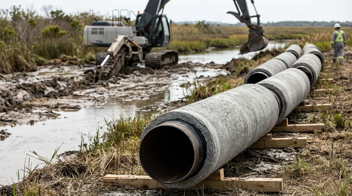
Continuous concrete coating goes on in the plant. It gives the pipe negative buoyancy along its full length, and it protects the corrosion coating from rock and abrasion during pull or float installation. It is the default choice when a long section stays saturated permanently, when the pipe will be floated or pulled into position, or when the ground offers no dependable restraint.
The drawbacks are practical:
- The pipe is heavy, and the coating is brittle. Handling, stringing and bending need heavier equipment and more care.
- Field-joint areas need infill that matches the coating's weight. Any gap there becomes a local buoyancy deficit.
- Heavier pipe on soft ground needs a bigger working platform, which runs straight into narrow wetland working widths.
- Field bends and fittings often can't be coated in the plant, so they need a separate solution.
Discrete weights, anchors and other restraint
Where only part of a crossing is saturated, discrete restraint is usually cheaper and easier to place than coating the whole route. The main options:
- Saddle or set-on weights. Concrete or cast weights clamped onto the pipe at calculated spacing. They suit short wet sections and go on quickly, but each weight is a point load on the coating. Check how the spacing interacts with the pipe's bending stiffness during lowering-in.
- Screw or helical anchors with straps. These restrain the pipe through the soil's holding capacity. They earn their keep in soft ground where weights alone would be excessive. Capacity depends on the soil's shear strength at anchor depth, so the ground investigation has to go that deep.
- Geotextile or sack ballast. Some projects use this as a flexible alternative to rigid weights where access for handling is tight.
- Trench breakers and compacted backfill zones. They limit water movement along the trench and stop it draining into low points. They do not offset uplift on their own.
Depth of cover and its limits
Burial gives mechanical protection against scour, anchor strikes and vehicle loads. It also adds soil weight over the pipe. In dry, well-compacted ground, that weight contributes materially to buoyancy resistance. In saturated organic or soft clay, it contributes much less. The submerged weight of the soil is lower, and the soil can lose strength if it's disturbed or liquefies. Treat cover as a protection and exposure requirement. Don't count on it as the primary buoyancy control in low-strength soils. Deeper burial there also costs more, because a wider, deeper trench is harder to keep open and harder to restore.
Burial also helps with temperature stability and navigation safety in coastal waters, as noted in practitioner guidance on deep-water trenching, and it limits exposure on unstable seabeds. At the landfall, exposed pipe has to be checked for on-bottom stability until the trench is backfilled.
Installation techniques for waterlogged and low-strength soils
| Technique | Where it fits | Main buoyancy implication | Main constraint |
|---|---|---|---|
| Conventional open-cut, dewatered trench | Unsaturated or locally drainable wetlands | Pipe is placed in a trench with controlled water; weights as needed | Dewatering discharge rules; trench stability |
| Open-cut with pipe floated in (push-pull) | Saturated wetlands with enough water to float pipe | Pipe is floated and then sunk or ballasted into the trench | Requires a water-filled trench; needs controlled sinking |
| Open-cut with concrete-coated pipe | Long saturated stretches | Negative buoyancy built in | Heavy handling; working platform needed |
| Trenchless (HDD, Direct Pipe, micro-tunnelling) | Where open-cut is impractical due to constructability, terrain or environmental drivers | Pipe is installed below the surface, so open-trench flotation is not an issue | Entry and exit workspace; geotechnical risk; cost |
Trenchless methods get used where typical methods aren't practical because of constructability, terrain or environmental constraints. Trenchless doesn't wipe out buoyancy entirely, though. Pipe pulled into a drilled hole in a fluid-filled bore, or strung out on rollers in water, can still float before it's pulled.
Open-cut wetland practice, as described in the FERC procedures and in utility best-practice material, has a few recurring features:
- Assemble pipe in an upland area where practicable, then bring it into the wetland as a prefabricated section.
- Keep the wetland working width narrow. Use timber mats or low-ground-pressure equipment. Don't use imported fill to carry equipment.
- Segregate topsoil from saturated or unsaturated areas as the procedures require. Restore it last, so the seed bank and original contours survive.
- Limit how long the trench stays open. Fabricate, test and coat in advance so lowering-in and backfill follow the excavator closely.
Illustrative worked example
This is an illustrative calculation, not a project record. It shows the logic of sizing a continuous concrete coating for a flooded trench. All inputs are assumptions.
Assumptions: outside diameter of bare steel pipe 1.000 m; wall thickness 0.015 m; steel density 7850 kg/m³; freshwater density 1000 kg/m³; concrete density 3040 kg/m³; pipe empty (air-filled); corrosion coating weight ignored. The result is for neutral buoyancy with zero margin. The design margin required by the project specification must be applied on top.
- Displaced volume per metre of bare pipe: π/4 × 1.000² = 0.7854 m³/m.
- Buoyant force expressed as mass per metre in freshwater: 0.7854 m³/m × 1000 kg/m³ = 785.4 kg/m.
- Inside diameter: 1.000 − 2 × 0.015 = 0.970 m.
- Steel cross-section area: π/4 × (1.000² − 0.970²) = 0.7854 × 0.0591 = 0.04642 m².
- Steel mass per metre: 0.04642 m² × 7850 kg/m³ = 364.4 kg/m.
- Net uplift of bare pipe in freshwater: 785.4 − 364.4 = 421.0 kg/m.
- Submerged density of concrete: 3040 − 1000 = 2040 kg/m³. Required coating volume for neutral buoyancy: 421.0 kg/m ÷ 2040 kg/m³ = 0.2064 m³/m.
- Coating thickness t from π/4 × [(1.000 + 2t)² − 1.000²] = 0.2064: (1 + 2t)² = 1 + (0.2064 × 4 ÷ π) = 1.2628, so 1 + 2t = 1.1237 and t = 0.0619 m, about 62 mm.
- Slurry check. If the trench holds slurry at an assumed 1200 kg/m³, the uplift of the bare pipe becomes 0.7854 × 1200 − 364.4 = 942.5 − 364.4 = 578.1 kg/m, which is higher than the 421.0 kg/m from step 6.
Result and interpretation: about 62 mm of concrete only reaches neutral buoyancy in freshwater, and with no margin. Step 9 shows that a denser trench fluid pushes uplift up by about 157 kg/m, so the coating chosen for clean water would not hold in slurry. The design fluid density, the margin and the coating thickness have to come from the project geotechnical and design basis. This example doesn't set them.
Practical checklist and decision guidance
Use these as prompts at design review, and again before lowering-in.
- Define the design fluid density for the trench from ground investigation, including the worst credible case of slurry or saline water.
- Check the empty-pipe condition at every stage: stringing, welding, hydrotest preparation and any outage after commissioning.
- Decide whether continuous coating, discrete weights, anchors or trenchless installation fits each section. Mixing methods along one route is normal.
- Confirm anchor holding capacity against measured soil strength at anchor depth, not just surface conditions.
- Don't count soil cover as buoyancy restraint in soft, organic or liquefiable ground without evidence.
- Check that the working platform can carry the heavier coated pipe inside the permitted wetland working width.
- Verify field-joint infill and fitting weights so there are no local buoyancy gaps.
- Confirm trench dewatering discharge, topsoil segregation and open-trench duration limits against the permit conditions before mobilisation.
- Plan trench breakers and backfill control so water doesn't flow along the pipe trench after restoration.
- For tie-ins to any in-service line at the wetland margin, apply the full isolation sequence: isolate, depressurise, verify zero energy, apply LOTO, control hazardous-area ignition sources, gas-test before and during work, and vent safely to a controlled location.
- Record as-built depth, weight type and location so later integrity assessments can check for flotation or exposure.
Conclusion
In wetlands and coastal crossings, buoyancy control is a design-basis decision, and it belongs early in the schedule. The inputs that drive it are the design fluid density, soil strength, permitted working width and trench open time. Concrete coating gives the most robust, continuous control, but it needs a larger platform and careful handling. Discrete weights and anchors suit shorter wet sections, but they're only as good as the ground data behind them. Cover depth provides protection and some restraint, yet it shouldn't be the only control in low-strength soil. Where open-cut becomes impractical, trenchless methods remove the trench but bring their own geotechnical and workspace demands.
Next, collect the geotechnical and groundwater data for each crossing, set the design fluid density and margin in the design basis, and use the table above to shortlist installation methods per section. Check each shortlist against the applicable codes, pipeline safety regulations and permit conditions before procurement.