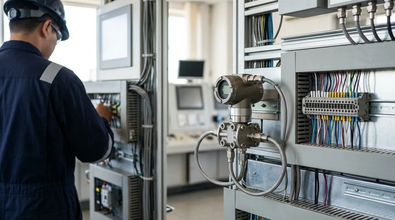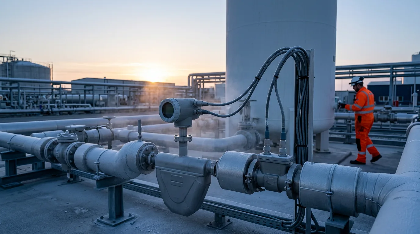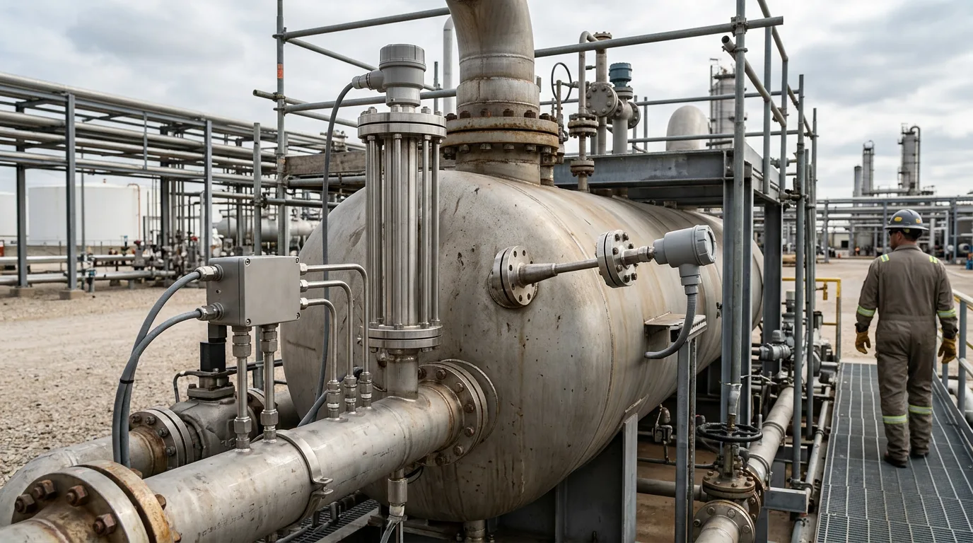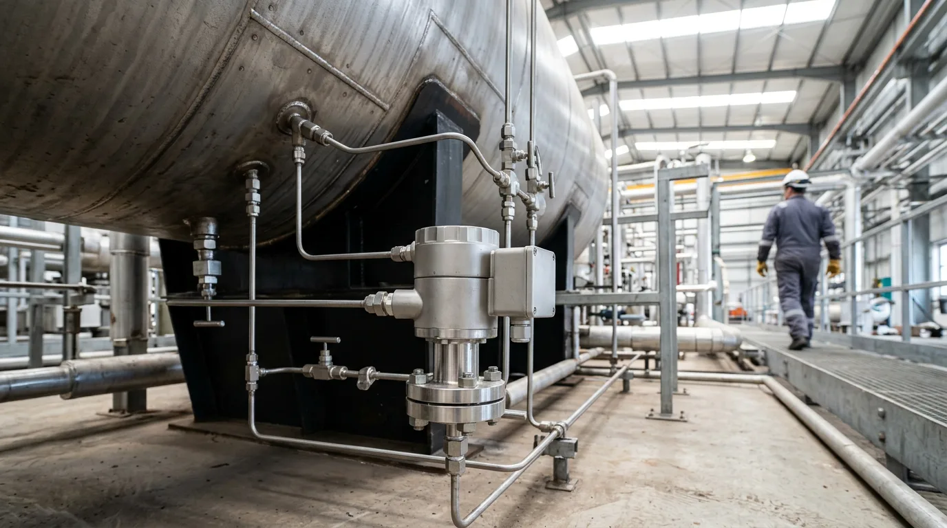
Level in a three-phase separator is the reading most likely to disagree with what the vessel is actually doing. Foam on the gas-oil surface and an emulsion pad between oil and water can make a transmitter show a clean, steady level that the vessel doesn't have. The results are ordinary problems: water carried over into the oil outlet, oil in the produced water, liquid carry-over into the gas line, and operators who stop trusting the level loop and put it in manual. A better transmitter rarely fixes this on its own. What works is a technology matched to the fluid, installed where it sees representative conditions, and commissioned against real fluid properties instead of data-sheet values.
Standards and requirements context
Separator level instruments do two jobs, and the requirements for each differ.
- Process control level keeps the vessel inside its operating window and sets the oil-water interface for downstream treating. Here the priorities are repeatability and how well the instrument tolerates foam and emulsion.
- Safety-related level, such as high-high liquid level protecting the gas outlet or low-low protecting against gas blow-by, falls under the lifecycle approach of
IEC 61511(functional safety, safety instrumented systems for the process industry sector). An instrument that reads well in clean water but falls apart in foam is a poor foundation for a safety function. Where the safety case demands it, keep safety and control measurements independent.
A few more requirements apply:
- Hazardous-area equipment on the vessel must be selected and installed to the
IEC 60079series for explosive atmospheres, particularly IEC 60079-14 (electrical installations) and the relevant equipment group and category standards (e.g. IEC 60079-2 for pressurised enclosures). - Vessel design and nozzle provisions follow the applicable separator specification,
API 12J(oil and gas separators). Check the nozzle count, sizes and stilling-well arrangements it allows before you commit to a technology. - Offshore, the safety-system analysis in
API RP 14Cdefines which level sensing functions your protection scheme needs.
Why foam and emulsion defeat level measurement
Emulsions are a normal part of crude separation. The Ametek crude dehydration page makes the point that gravity separation has trouble removing them. Heavy crude makes it worse. Endress+Hauser's heavy crude separation note puts the class at API 15 or below, corresponding to density at or above approximately 966 kg/m³, which is close to water density. When the density difference is that small, the oil-water boundary stops being a sharp line. It becomes a graded zone of oil-continuous emulsion, water-continuous emulsion and free water. The Endress+Hauser interface measurement article describes this multi-layer interface makeup directly.
Each sensing principle reacts to that zone in its own way.
- Foam changes the apparent gas-liquid surface. It reflects, scatters or absorbs radar energy, and it lowers the effective density that pressure-based devices see.
- Emulsion shifts the bulk density and dielectric properties of the liquid. Density-based and dielectric-based methods both end up reading an average of a mixture, never a clean phase.
- Flow conditions matter too. A good sensor in a bad location still reads badly.
Comparing the three technologies
Differential pressure (DP)
A DP transmitter infers level from hydrostatic head. For a single liquid, level follows from:
h = ΔP / (ρ × g)
where h is the liquid height, ΔP the head pressure difference, ρ the liquid density and g gravitational acceleration. Everything hangs on ρ. In a separator, ρ is never constant. It moves with water cut, temperature, foam carry-under and emulsion thickness.
Strengths:
- No moving parts and no dependence on surface reflection.
- Surface foam doesn't act as a reflector, so it doesn't disturb the measurement directly.
- Familiar to technicians and simple to proof-test.
Weaknesses:
- The reading is a density-weighted average. A growing emulsion pad or a shifting water cut moves the reading with no change in true level.
- Impulse lines on waxy or emulsifying crude plug, and wet legs can change density with temperature. Remote diaphragm seals avoid plugging but bring temperature and capillary effects that must be configured correctly.
- Interface measurement needs two DP cells, or one cell plus a known total level. Errors in the density inputs compound.
DP is a sound choice for total level when fluid density is reasonably stable and well characterised. It is a weaker choice for interface duty on variable heavy crude.
Radar (guided wave and non-contacting)
Non-contacting radar uses free-space microwaves to measure continuous level, as the Emerson level catalogue describes. It suits the gas-liquid surface when that surface is clean. Foam is its main enemy. A low-density foam layer can attenuate or diffuse the return, leaving the signal weak, lost or biased. A stilling well or bypass chamber can calm the surface and shield the radar from the foam blanket, but the chamber has to be designed so it doesn't trap a different liquid composition from the vessel.
Guided wave radar (GWR) sends the pulse down a probe and is the usual radar option for interface. It works from the dielectric difference between oil and water, which is fine when the boundary is distinct. With a thick emulsion, the pulse may reflect partway through the graded layer. The instrument then reports the top of the emulsion, the middle, or a wandering position, depending on threshold settings.
Strengths:
- Output is largely independent of density, so a changing water cut doesn't directly bias the reading.
- No moving parts, and good resolution when a clear boundary exists.
- GWR can report both total level and interface from one probe.
Weaknesses:
- Foam and emulsion degrade the return signal.
- Coating or buildup on the probe, common with heavy and waxy crude, can mask the true reflection.
- Setup depends on dielectric properties that change with temperature and composition.
Internal float and displacer devices
A float rides on the liquid surface, and an interface float is built to a density between oil and water so it sits on the boundary. A displacer measures the buoyancy force on a submerged element. Both depend on density.
Strengths:
- The principle is simple, with no electronics inside the process.
- They are often tolerant of foam on the surface, because the float responds to liquid density rather than to a reflected signal.
- They give a direct, intuitive response that operators trust.
Weaknesses:
- An interface float settles where its density matches the local fluid. In a graded emulsion, that point is wherever the emulsion happens to match, which may not be the boundary you actually want to control.
- Fouling and wax add weight and change buoyancy. Mechanical wear, sticking in guides and turbulence are all failure modes, and maintaining internals means opening the vessel.
- Density changes shift the calibration of a displacer.
Summary table
| Aspect | DP | Radar (non-contacting / GWR) | Internal float / displacer |
|---|---|---|---|
| Principle | Hydrostatic head | Microwave reflection | Buoyancy |
| Foam on gas-liquid surface | Little direct effect, density bias if foam is carried down | Signal loss or bias, especially non-contacting | Generally tolerant |
| Thick emulsion at interface | Reads averaged density | GWR may report the wrong point in the layer | Settles at matching density, not necessarily the boundary |
| Dependence on fluid density | Direct | Low | Direct |
| Dependence on dielectric | None | Direct for GWR | None |
| Fouling and wax | Impulse line plugging, seal effects | Probe coating masks reflection | Added weight, sticking |
| Maintenance access | Usually external | Often external via chamber or nozzle | Usually requires vessel entry or chamber access |
Illustrative scenario
The following is an illustrative scenario, not a reported field case. A three-phase separator on heavy crude service runs a GWR on a bridle for interface and a non-contacting radar on the top nozzle for total level. After a change in production mix, the total level looks stable, but the interface reading drifts and the water leg dumps intermittently. Oil shows up in the water outlet.
The data shows the GWR tracking the top of a growing emulsion layer rather than the free-water boundary, while the top radar reads a clean level. A vessel sample confirms a thick emulsion pad. Two actions follow:
- Treat the cause with demulsifier adjustment and heat, rather than retuning the transmitter to hide the layer.
- Add a DP-based density cross-check across the lower vessel. If the GWR interface and the density profile disagree, the emulsion layer is significant, and operators have an early warning to act on.
The lesson is that two diverse principles disagreeing is useful information. A single technology agreeing with itself is not proof of correctness.
Commissioning tips to avoid false level indication
Get real fluid data before configuring anything:
- Take samples at operating temperature and pressure, and determine oil and water densities and the emulsion behaviour. Don't use data-sheet densities for DP spans.
- Record how density and dielectric properties shift with temperature and water cut during startup and turndown.
Configure with the failure modes in mind:
- For DP, set density compensation deliberately, and decide how foam and emulsion will be handled. Verify that impulse lines or seals are filled, vented and traced correctly.
- For radar, set the echo threshold and blocking distance with the vessel at representative conditions. Confirm the device tracks the intended echo, not a nozzle or probe-end reflection.
- For floats, check free travel through the full range and confirm the interface float's density suits the actual boundary fluids.
Verify against an independent reference:
- Compare each transmitter against sight glasses, sampling taps or a second technology at several levels, not just one point.
- If the process allows, make a deliberate level change and confirm the response is correct in direction and speed.
Address the process, not only the instrument:
- Check inlet device and baffle arrangements. The JPT Savvy Separator article shows that.
- Evaluate foam control through chemical dosing and residence time, and use stilling wells or bypass chambers to isolate sensors from disturbed zones.
- Heat tracing and insulation on chambers and lines prevent the wax and viscosity changes that corrupt readings.
Safety warning — commissioning and maintenance: Any work that opens a chamber, removes a probe or disconnects impulse lines exposes hydrocarbons and may require confined-space entry. Isolate the instrument from the vessel with positive isolation, depressurise to a safe location, and verify zero energy before breaking containment. Apply lockout/tagout, work under the hazardous-area permit with equipment suitable for the zone, and use continuous gas detection. Vent and drain to the closed system or flare, not to atmosphere. Do not proceed without a formal hazard assessment, rescue plan and competent supervision.
Selection checklist
- Define whether the measurement is for control, alarm or a safety function, and apply
IEC 61511where it is safety-related. - Characterise the crude: density, wax tendency, water cut range and emulsion stability, including the heavy-crude case.
- Identify whether foam, emulsion or both dominate. Foam penalises non-contacting radar, and emulsion penalises GWR and interface floats.
- Choose diverse principles for critical separators, such as radar for total level with DP-based density checking.
- Specify chambers, stilling wells and nozzle positions at the design stage, within the vessel specification (
API 12J). - Confirm hazardous-area certification against the
IEC 60079series. - Plan access for cleaning, probe inspection and proof testing without vessel entry where possible.
- Document commissioning baselines and review them after any change in crude source.
Conclusion
No single technology is immune to foam and emulsion. DP depends on density, radar depends on a clean signal and dielectric contrast, and floats depend on density and clean mechanics. Start from the fluid data and the failure mode each technology fears, then pick the measurement and its installation to suit. Where a false reading would be costly, use two diverse principles and treat their disagreement as a diagnostic.
For your next step, pull current fluid samples and review the interface behaviour on your worst-performing separator. Then compare each transmitter against an independent reference before changing any configuration.