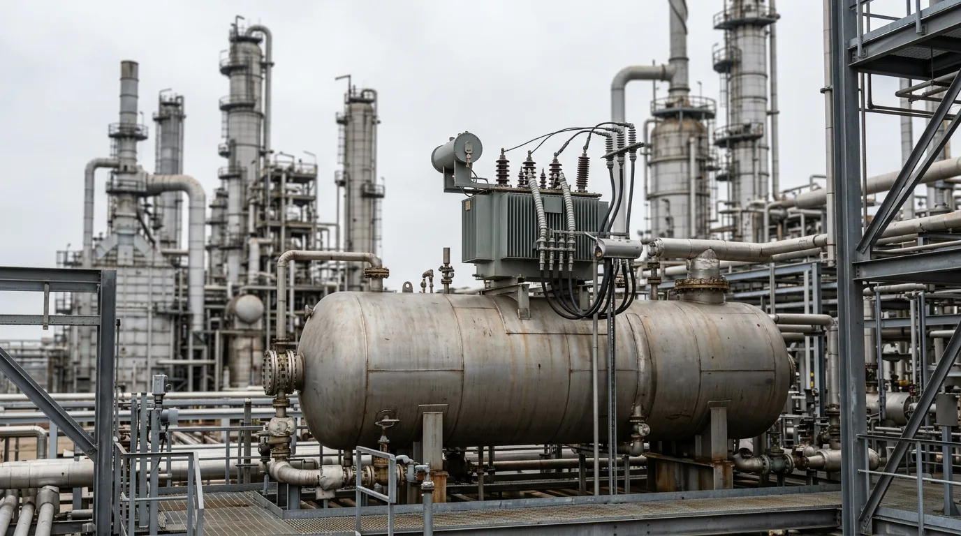
Fixed-equipment inspection at a refinery or petrochemical plant still comes down to access. Scaffolding, rope access and permit-required confined space entry eat a large share of turnaround effort, and they put people in the most hazardous spots on site. What comes out the other end is usually a sparse grid of spot thickness readings, written down by hand and hard to trend from one campaign to the next. That costs you twice. First, schedule and labour go into just getting an inspector to the location. Second, there's risk. Damage that sits between grid points, or on a surface nobody could reach, stays hidden until it shows up as a leak or an unplanned outage.
Drones, crawlers and permanently mounted sensors each go after a different part of this problem, and they are not interchangeable. This article compares them with conventional methods so inspection and reliability engineers can work out where each one earns its place.
Standards and requirements context
None of the main inspection codes mandates a particular data-collection technology. They define what the owner-user must know. The technology has to deliver that knowledge reliably.
API 510(pressure vessel inspection code),API 570(piping inspection code) andAPI 653(aboveground storage tank inspection, repair, alteration and reconstruction) set the in-service inspection, rating and repair framework for the equipment classes they cover.API 580(risk-based inspection) andAPI 581(risk-based inspection methodology) give the basis for matching inspection effort to damage likelihood and consequence. Better data feeds straight into this, since corrosion rates and confidence in remaining life both depend on data quality.API 571(damage mechanisms affecting fixed equipment in the refining industry) tells you what to look for, which in turn tells you which technology can see it.API 579-1/ASME FFS-1(fitness-for-service) is the route for assessing a flaw once you've found one. It needs defensible thickness and flaw-sizing data.- ASME Section V governs nondestructive examination methods and procedures.
- The
IEC 60079series (explosive atmospheres) governs any powered device entering a classified area, drones and crawlers included.
In practice, a robot or drone is just a way of collecting data. You still need a qualified procedure, a competent operator, and an inspector who accepts the result. Visual imagery used for screening doesn't replace a calibrated thickness measurement where the code calls for one.
Technical body
Drone-based visual inspection
Drones make the most sense when the question is "what does the surface look like?" and access is the real constraint. Think flare stacks, tall columns, furnace exteriors, tank roofs and shells, pipe racks and structural steel.
Engineering strengths:
- Rope access and scaffolding for a general visual survey are largely eliminated, which cuts exposure to work at height.
- Georeferenced imagery gives you a repeatable record. The same view can be compared across campaigns, which supports trending of coating breakdown and external corrosion.
- Thermal imaging can pick up wet insulation or process anomalies that don't show in visible light. It's an indicator, though, not a measurement of wall loss.
Limits to respect:
- A camera does not measure wall thickness. Drone imagery can tell you where to put contact UT, but it doesn't replace it.
- Image interpretation quality depends on lighting, resolution, standoff distance, and whoever or whatever is reviewing the pictures. A 2022 Springer Nature review of machine learning techniques for robotic and autonomous inspection covers the role of automated defect recognition. Treat automated classification as decision support that a qualified inspector verifies.
- Flight inside or near live hydrocarbon equipment needs an intrinsically safe or otherwise certified platform and a controlled area.
Internal drone surveys of vessels and tanks are the use case that most directly replaces entry for a general visual look.
Robotic crawlers and robotic UT
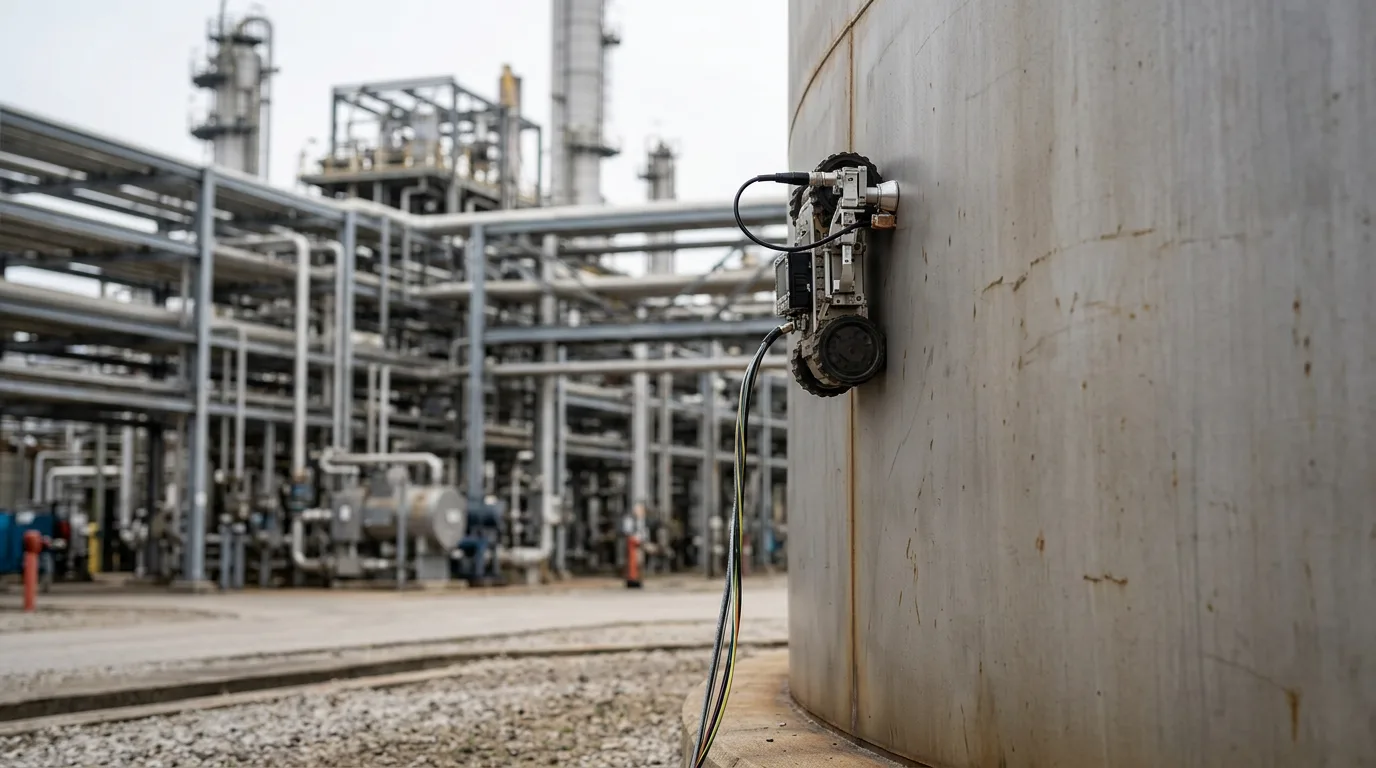
Magnetic or other adhesion crawlers carry UT probes across vessel shells, tank walls and piping. Their real value is data density. Rather than a manual grid, a crawler can acquire continuous or closely spaced thickness data and build a corrosion map. That changes what you can actually see: localised pitting, a thinning band at a liquid-vapour interface, or an area of general loss that a coarse grid would simply step over.
Engineering strengths:
- Coverage and repeatability. A mapped scan can be overlaid on the previous one to establish a real corrosion rate with spatial resolution.
- Reduced access burden on tall or awkward surfaces, and the operator works from a safe location.
- Raw data can be stored for later re-evaluation, which helps fitness-for-service work.
Limits:
- Surface condition matters. Scale, heavy coating, weld caps, nozzles and obstructions all affect adhesion and coupling, and some geometries stay out of reach.
- Couplant management and probe calibration need the same discipline as manual UT. There's no shortcut here.
- Mechanisms such as cracking may need specific advanced UT techniques. Confirm the technique can detect the damage mechanism identified in your
API 571review before you assume a scan "covers" it.
Permanently mounted sensors
Fixed sensors, such as ultrasonic thickness monitors, corrosion probes and others, answer a different question: "how fast is it changing?" They sit at selected locations and report continuously or at set intervals, with no inspector standing there.
Engineering strengths:
- Trends show up between shutdowns, so process excursions that accelerate corrosion can be correlated with operating data.
- No personnel need to be at the location. That suits hard-to-reach or high-consequence points such as injection points, mixing points and dead legs.
- Because the measurement point never moves, the scatter caused by repositioning a probe goes away.
Limits:
- A sensor covers a point. It can't find damage a metre away. Placement depends on a sound damage-mechanism review and risk ranking.
- Sensors need power or battery management, communications, hazardous-area certification and a calibration and verification plan. They're extra equipment, and that equipment needs maintenance too.
- Monitoring data has to tie back to inspection decisions. Alarm philosophy and response ownership need agreeing before commissioning, not after.
Comparison
| Aspect | Conventional manual | Drone visual | Robotic crawler UT | Permanent sensors |
|---|---|---|---|---|
| Primary output | Spot readings, visual notes | Imagery, thermal screening | Dense thickness maps | Continuous trend at fixed points |
| Best for | Verification, confirmation, complex geometry | Access-limited surface survey | Shell and wall thinning mapping | Rate-of-change at high-risk points |
| Spatial coverage | Sparse | Broad, surface only | Broad, wall condition | Point only |
| Measures wall thickness | Yes | No | Yes | Yes |
| Personnel exposure | Highest | Low | Low to moderate (deployment) | Low after installation |
| Main constraint | Access cost | Interpretation, no thickness | Surface condition, geometry | Placement, upkeep |
| Repeatability | Operator-dependent | Good with georeferencing | Good | Very good |
No single column wins. The strongest programmes layer them. Drones survey and prioritise, crawlers quantify, permanent sensors watch the worst locations, and manual NDE verifies and handles the geometry robots can't reach. Both point toward combining modalities rather than swapping one for another.
Safety when deploying robots or drones on hydrocarbon equipment
Any activity that opens or enters hydrocarbon-containing equipment, including an internal drone flight, needs the same controls as human entry. At minimum:
- Isolate the equipment with positive isolation (blinds or spades, not just valves).
- Depressurise and drain, and vent safely to a controlled destination such as flare or closed drain.
- Verify zero energy and confirm isolation effectiveness.
- Apply lockout/tagout to all energy sources, including the robot's own power.
- Gas-test before and during work, and clean, purge and ventilate to the permit requirements.
- Use equipment certified for the hazardous area classification under the
IEC 60079series where a flammable atmosphere may exist.
Remote deployment reduces the number of people exposed. It does not remove the need for the permit system.
Practical example (illustrative)
The following scenario is illustrative and not drawn from a listed source.
A refinery has a tall fractionating column with a long history of external coating breakdown and a known corrosion-prone zone near a product draw. The conventional plan is scaffolding up the full height, followed by grid UT at selected elevations.
The alternative plan looks like this:
- A drone survey of the exterior before shutdown identifies coating failure, insulation damage and a few areas of suspicious staining, and produces a georeferenced image record.
- The inspection team uses the survey alongside the damage-mechanism review to rank zones. The draw region and the areas of insulation damage go to the top of the list.
- A crawler scans the highest-ranked zones to produce thickness maps. Any area showing localised loss gets flagged.
- Inspectors verify the worst indications with manual UT at the flagged spots, and assess flaws through the fitness-for-service route if needed.
- After the turnaround, permanent thickness sensors go in near the worst location so the corrosion rate can be tracked against operating conditions.
Scaffold is then needed only where manual verification or repair requires it. The inspection record is also denser and easier to compare at the next campaign. The trade-off is upfront effort in planning, data management and operator qualification.
Decision checklist
- Define the question first: surface condition, wall loss mapping, or rate of change at a known point. Then pick the technology that measures it.
- Confirm the technique can detect the damage mechanism identified in your
API 571review. - Check that the method yields data your code and fitness-for-service procedures accept. If it doesn't, plan for manual verification.
- Establish who is qualified to operate the equipment, and who reviews and accepts the data.
- Verify surface condition, coating, geometry and obstructions for crawler access before mobilising.
- Confirm hazardous-area certification for every powered device entering a classified area.
- Prepare isolation, depressurisation, zero-energy verification, LOTO, gas testing and venting before any entry or internal flight.
- Choose permanent sensor locations from a risk ranking, not convenience, and define alarm response ownership in advance.
- Specify data formats, georeferencing and storage so results can be compared across campaigns.
- Treat automated defect recognition as decision support and require inspector review.
- Pilot on one asset, compare results with the conventional method, and document the gaps before scaling.
Conclusion
Drones, crawlers and permanent sensors each address a specific weakness of conventional inspection: access exposure, sparse data and blind periods between shutdowns. None of them replaces verification by a qualified inspector where the code requires it. The most defensible approach is layered. Use drones to survey and prioritise, crawlers to quantify wall loss, permanent sensors for the highest-risk points, and manual NDE to confirm.
As a next step, pick one asset with a well-understood damage mechanism and a high access burden. Run the layered approach alongside your existing method for one cycle. Compare data quality, exposure and effort, and use that evidence to update your risk-based inspection plan.