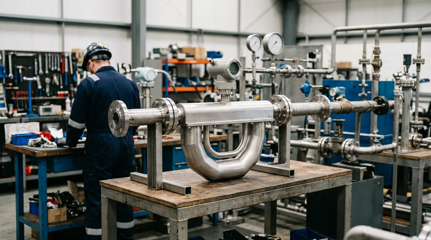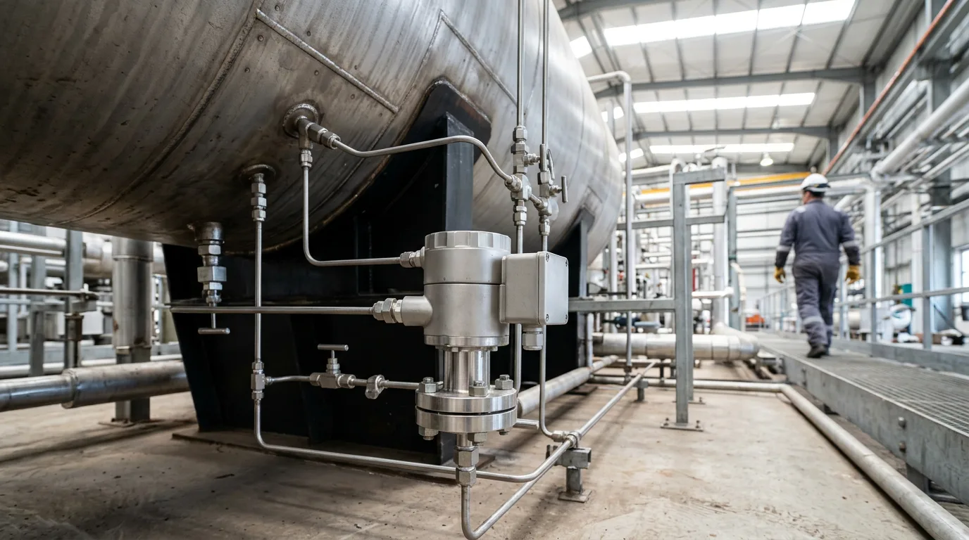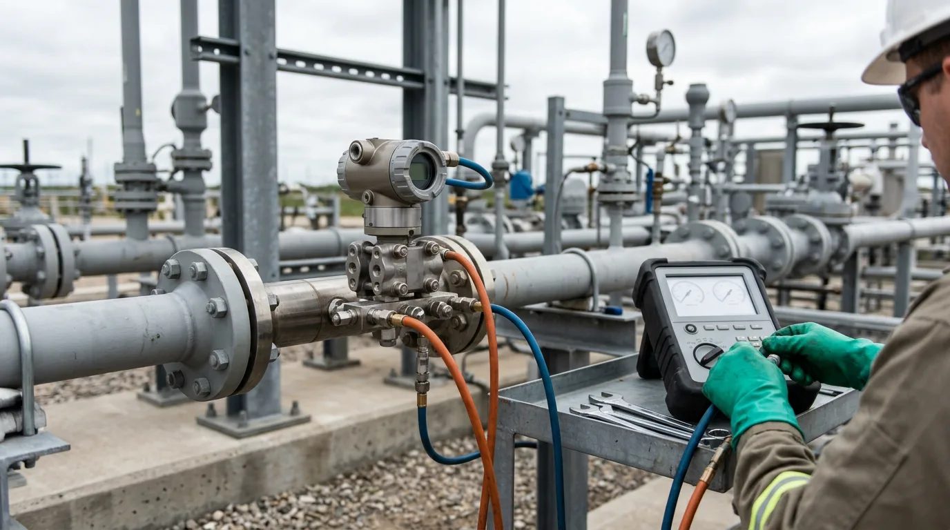
Gas custody transfer is billed on a square-root relationship. A differential pressure (DP) transmitter that has drifted on an orifice meter run misstates volume every hour it sees flow. The damage is worst at low DP, where a fixed zero shift takes a big bite out of the reading. A bad calibration can add error too. A leaking equalizer, a reference standard too coarse for the range, or a transmitter trimmed without accounting for static pressure effects will all do it. This article lays out a field procedure for DP transmitters on gas orifice runs, the error sources that most often defeat it, and the records that let the result stand up to scrutiny.
Standards and Requirements Context
The measurement system on an orifice run is governed by the orifice metering standards and the electronic measurement standard for flow computers:
API MPMS Chapter 14.3(the same document as AGA Report No. 3) covers orifice metering of natural gas and related hydrocarbon fluids. It sets the geometry, installation and flow equations that turn a DP reading into a flow rate.ISO 5167covers measurement of fluid flow by means of pressure differential devices inserted in circular cross-section conduits running full. It is the international counterpart for primary element requirements.API MPMS Chapter 21.1covers flow measurement using electronic metering systems, specifically electronic gas measurement. It is the usual reference for flow computer verification and calibration practice, including audit trails.ISO/IEC 17025sets the competence requirements for calibration laboratories. It matters here because the traceability and uncertainty expectations it describes are what your reference standards and certificates need to support.
Contract measurement agreements and company measurement procedures normally set the actual calibration frequency, the as-found tolerance and the notification requirements. For acceptance limits, go to those documents, not to general guidance.
The Emerson Engineer's Guide to DP Flow Measurement (2022 edition) makes a point that gets lost easily in the field. The flow equation depends on the primary element's discharge coefficient, and that coefficient comes from laboratory work on that specific geometry. Calibrating the transmitter verifies only the DP measurement. It tells you nothing about plate edge condition, bore, or straight-run effects. Those need their own inspection.
Technical Body
What the Calibration Must Cover
On a gas run, the flow computer works out flow from three measured inputs: DP, static pressure and temperature. The Minerva guide on calibrating gas custody transfer flow computers treats them as one system. It shows a pressure calibrator on the pressure inputs and a platinum resistance thermometer (PRT) probe on the temperature input. So the DP transmitter gets calibrated as one input to the flow computer, not as a standalone device. Check the whole chain: transmitter output, the signal path to the flow computer, scaling, and the value actually displayed.
The Transcat guidance on DP gas custody transfer calibration (by Joel Hartel) concentrates on the instrument, measurement and technique issues that decide whether a result is credible. The central one: the reference standard has to suit the DP range and be more accurate than the device under test by an adequate margin.
Safety and Isolation Before Any Connection
Connecting a calibrator to a DP transmitter means working on a manifold holding hydrocarbon gas at line pressure. Treat it as hydrocarbon-containing equipment, because it is.
- Permit and hazardous area. Work under the site permit system. Use calibrators and communicators certified for the area classification, and confirm that the certification matches the zone.
- Gas detection. Carry a portable gas detector for all manifold work, especially while venting.
- Isolation. Close the root or tap block valves on both sides of the primary element. Apply LOTO or the site equivalent where the permit calls for it, and tag the valves.
- Depressurisation. Bleed the transmitter side through the manifold vent or drain ports to a safe location, such as a closed vent or flare header. Never vent gas into an enclosure or onto a walkway.
- Verification of zero energy. Confirm the reference gauge reads zero and the vent flow has stopped. A plugged impulse line can hold trapped pressure while the vent looks dead.
- Process-side communication. Tell the control room and, where the measurement agreement requires it, the counterparty. Put the flow computer into the agreed maintenance mode so test pressures don't get booked as gas volume.
Field Calibration Procedure
- Gather records. Pull the transmitter configuration (calibrated range, units, damping, output mode), the flow computer scaling, the last calibration report and the reference standard's certificate. Confirm the DP range and units match in both devices. A mismatch is a common source of systematic error, and a calibrator-only test won't catch it.
- Capture as-found zero under static pressure. Before you vent anything, close the block valves, open the equalizer and read the transmitter output with line pressure on both sides. That shows how the zero behaves once static pressure is applied. The Beamex article on footprinting in DP transmitter calibration (December 2025) covers this ground: a bench calibration at atmospheric pressure can miss behaviour that shows up in service.
- Check equalizer integrity. If the output shifts or pressure bleeds off while you work, a valve is passing. Sort that out before you trust any zero reading.
- Depressurise and verify zero energy as described above, then connect the calibrator. Apply the pressure source to the high side and leave the low side vented to atmosphere, unless your procedure calls for a different configuration.
- As-found points. Apply points across the range, upscale and downscale, and let each one settle. Record the reference value, the transmitter's digital reading, the loop or analog output and the value shown on the flow computer. Take points at low DP as well as mid and upper range, since flow errors are amplified at the low end (see the example below). Where the unit runs a hysteresis check, record the up and down values.
- Adjust only if the procedure requires it. The usual order is sensor zero trim, then span or upper trim, then output trim if the analog loop disagrees with the digital value. Don't re-range the transmitter to get around a trim. Re-ranging changes the scaling the flow computer depends on, so it goes through change control.
- As-left points. Repeat the full set. The as-left data is your evidence that the adjustment actually worked.
- Restore. Disconnect the calibrator and close the vents and drains. Leave the equalizer closed with both block valves open, as the manifold design requires. Leak-test at line pressure using an approved method, and open valves slowly so a pressure surge doesn't overrange the sensor on one side.
- Confirm and release. Check that DP, static pressure and flow look plausible against live flow. Take the flow computer out of maintenance mode and record the times.
Common Error Sources
| Error source | Effect on result | Mitigation |
|---|---|---|
| Static pressure effect on zero and span | Zero or span differs between a bench or atmospheric test and line conditions | Check zero with equalized line pressure; follow the manufacturer's guidance on static pressure effects |
| Passing equalizer or block valve | False zero or drifting reading | Test valve integrity; replace the valve before calibrating |
| Reference standard range too wide | Reference uncertainty consumes the tolerance at low DP | Use a reference module matched to the DP span, with a current certificate |
| Impulse line problems (plugging, liquid, leaks, temperature differences between legs) | Calibration passes but in-service DP is wrong | Inspect and blow down or purge lines under procedure; check for leaks and liquid pockets |
| Mounting orientation or position change | Zero shift | Re-zero after the transmitter is remounted |
| Unit or range mismatch between transmitter and flow computer | Systematic flow error despite a good calibration | Compare configuration in both devices; verify the displayed value |
| Inadequate settling time | Readings recorded before stable | Allow stabilization; record at consistent points |
| Low-flow cutoff and square-root handling differing between devices | Disagreement at low DP | Check where square-root extraction and cutoff are applied |
| Primary element condition | Real flow error not seen by transmitter calibration | Inspect the plate and meter tube separately |
Documentation Practices
The paperwork matters as much as the adjustment. Each calibration report should carry:
- Transmitter tag, serial number and firmware or configuration revision.
- Reference standard identity, certificate reference and calibration due date.
- As-found and as-left data at every point, in both directions.
- The static pressure condition under which the zero check was made.
- Adjustments made, and whether any change to range or damping was authorised.
- Flow computer values before and after, and the maintenance-mode period.
- Names, date, and the witnessing party if the contract requires one.
Keep the as-found data even when it passes. A run of as-found results across successive calibrations shows which way the drift is heading, and that trend is what supports decisions on interval and replacement. When an as-found result exceeds the agreed tolerance, flag it in the report so the measurement team can assess the effect on past volumes under the contract.
Illustrative Example: Why Low-DP Points Matter
This is an illustrative calculation, not field data. For an orifice meter, flow varies with the square root of DP:
Q/Qmax = √(DP/DPmax)
Assume a transmitter has a zero shift equal to 0.5 % of span, and that the flow computer does not correct for it.
- At a DP of 25 % of span: Q/Qmax = √0.25 = 0.50, so the flow is 50 % of maximum.
- The relative DP error is 0.5 / 25 = 0.02.
- Because flow varies as the square root of DP, the relative flow error is about half the relative DP error: 0.5 × 0.02 = 0.01, or about 1 %.
- At a DP of 4 % of span: the relative DP error is 0.5 / 4 = 0.125.
- The relative flow error is about 0.5 × 0.125 = 0.0625, or about 6 % (the exact square-root calculation gives √(4.5/4) = 1.061, or about 6.1 %).
The same 0.5 % zero shift costs about 1 % of reading at 25 % of span DP, and about 6 % at 4 % of span DP. A run that spends most of its time at low DP, such as a turned-down well-site meter, will carry far more error from zero shift than the span figure suggests. On those runs, the zero check and the low-end points deserve the most attention. The agreed tolerance and the low-flow cutoff come from your measurement agreement.
Pre-Job and Post-Job Checklist
- Permit issued; hazardous-area rating of calibrator and communicator confirmed.
- Control room and counterparty notified; flow computer in the agreed maintenance mode.
- Gas detector in use; vent route to a safe location identified.
- Block valves closed and locked or tagged; pressure vented and zero energy verified.
- Reference standard range suits the DP span; certificate is current.
- Transmitter and flow computer ranges and units compared.
- As-found zero recorded under equalized line pressure, then as-found points recorded in both directions.
- Equalizer and valve integrity confirmed before accepting the zero.
- Adjustments limited to trims; any re-ranging passed through change control.
- As-left points recorded; leak test completed at line pressure.
- Valves returned to the correct sequence; equalizer closed, vents closed.
- Flow computer values confirmed against live flow and released from maintenance mode.
- Report completed with as-found data, reference identity and sign-off.
- Plate and impulse line inspection scheduled separately where not done during this job.
Conclusion
A DP transmitter calibration protects custody-transfer revenue only when it's run as a complete job. That means safe isolation, a zero check under line pressure, a suitable reference, honest as-found data, and a transmitter and flow computer that agree with each other. Next, compare the DP range and units in your transmitters against the flow computer configuration. Check that the reference modules in your toolkit suit the DP spans you actually calibrate. Go back through the last several as-found records and look at the drift direction. Where runs spend most of their time at low DP, give those meters the closest zero check and the shortest review interval your measurement agreement allows. Then schedule the primary element and impulse line inspections on the same cycle, because the transmitter calibration will never reveal faults in either.