Long-Distance Tiebacks: Where Flow Assurance Really Gets Hard
Long subsea tiebacks mean a long, cold, multiphase flowline running from the wellhead to a host you can't easily reach when something goes wrong. A hydrate plug, a wax-gelled line, or an umbilical that fails to deliver inhibitor on time stops production for as long as remediation takes. On a tieback, that can mean weeks of depressurisation, vessel mobilisation and deferred output. The cost doesn't come from the design case. It comes from the transients: shutdown, restart, ramp-up and late-life low rates. The flow assurance discipline behind them has to be correspondingly rigorous.
Standards and requirements context
Few standards dictate flow assurance outcomes. Most of the requirement comes from the operator's design basis, checked against general subsea and pipeline codes:
ISO 13628-1(Petroleum and natural gas industries, design and operation of subsea production systems, Part 1: general requirements and recommendations) frames system-level design, including interfaces between wells, flowlines, control systems and host.DNV-ST-F101(Submarine pipeline systems) governs flowline and riser design, including the load cases that thermal expansion, shutdown and depressurisation create.ISO 13628-5(subsea umbilicals) covers the umbilical hardware that carries chemical injection lines and hydraulics. You still have to show line sizing and fluid compatibility in your own design calculations.
The flow assurance basis itself should be a project document. It sets out fluid characterisation, the hydrate and wax envelopes, allowable cooldown time, the inhibitor philosophy and the operating procedures that depend on them. Treat it as a controlled document that operations signs off on, not a design-phase appendix.
Why distance changes the problem
Offshore Magazine's review of long-distance tieback strategies makes the economic case. Tiebacks to existing facilities are how marginal fields get developed when they can't carry their own infrastructure. The flow assurance consequence is simple: distance multiplies every exposure.
- Residence time and heat loss. Fluid sits far longer in a line surrounded by seawater. Arrival temperature drops, and cooldown after shutdown becomes the governing case.
- Pressure. Hydrate conditions are easier to meet at high pressure and low temperature, and a long, deep flowline gives you both.
- Inventory. A large liquid inventory is slow to displace, slow to depressurise and expensive to treat with inhibitor.
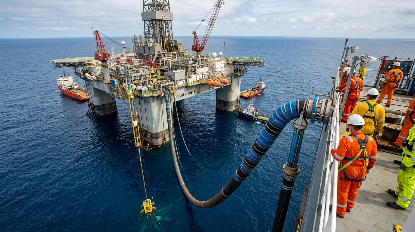
- Response lag. Chemicals injected at the host or at the subsea tree take a long time to reach the point of need through a long umbilical or flowline.
The OTC paper on an integrated solution for 100 km deepwater liquid tiebacks tackles this same set of problems. It treats thermal management, chemical delivery and operating strategy as one coupled design, not three separate workstreams. Petrobras's Palombeta case study makes a similar point from the operator's side, describing flow assurance as the central challenge of its longest and deepest tieback.
Hydrate management
Prevention philosophy
Most long tiebacks rely on two or three layers of defence. Picking between them is a lifecycle decision, not a design-day one.
| Approach | Where it works well | Main exposure |
|---|---|---|
| Thermodynamic inhibitor (methanol, MEG) | Gas and gas-condensate systems, and wells with significant water production | Large volumes, host storage and regeneration capacity, and umbilical sizing |
| Low-dosage hydrate inhibitor | Reducing injection volumes where fluids qualify | Fluid-specific qualification, limits at high subcooling, and compatibility with other chemicals |
| Passive insulation | Keeping fluids outside the hydrate region during steady flow and short shutdowns | Cooldown time is finite, so it only delays the problem |
| Active heating (electrically heated pipe-in-pipe or direct heating) | Long shutdowns, restart after extended outages, and low-rate late-life operation | Power supply, cable and connector reliability, and added cost and complexity |
Insulation alone buys you time. It doesn't remove the problem. Whatever approach you prefer, the design has to state what happens once the allowable cooldown time is exceeded.
Operational transitions are where plugs form
Steady-state flow rarely forms hydrates. Plugs form when operations drift away from the design basis:
- Unplanned shutdown. The line cools toward seawater temperature while still pressurised. The operator needs a defined decision point: inhibit and displace, or depressurise.
- Restart. Cold fluids and gas expansion across chokes can push the fluid back into the hydrate region. Inhibitor has to be in place before flow resumes, not after.
- Low-rate and late-life operation. Falling rates lengthen residence time and raise heat loss per unit of production. Rising water cut changes the inhibitor demand.
- Planned shutdown. This gives you the best conditions for preservation, typically displacing the line or treating it with inhibitor before the cooldown clock starts.
Build displacement and depressurisation routes into the design so the host can actually run them. A dead-oil or treated-fluid flush needs a pump, a route, a return path and somewhere to put the fluid.
Plug remediation safety
If a plug does form, remediation is hazardous. Depressurise from both sides of the suspected plug so no differential pressure drives it down the line as a projectile. Before anyone starts work:
- Isolate and depressurise the affected section through the designed routes.
- Verify zero stored energy at the work point with calibrated gauges, and confirm there are no trapped pressure pockets.
- Apply LOTO to all isolation points.
- Control ignition sources in hazardous areas and use continuous gas detection.
- Vent safely to the flare or the designated vent system.
Treat remediation as a controlled engineering procedure, not an improvised response.
Thermal design
Steady state is not the governing case
A line that holds temperature at plateau rate tells you little about how it behaves at turndown or after shutdown. Thermal design should cover:
- Arrival temperature across the full production profile, including late-life low rates and high water cut.
- Cooldown time to the hydrate and wax appearance temperatures, with margin the operator can actually use when making decisions.
- Restart warm-up, since insulation holds heat in both directions.
- The effect of fluid properties, including water cut, on heat capacity and the hydrate region.
Insulation versus heating
Wet insulation, pipe-in-pipe and bundle solutions all trade heat-loss performance against cost, installation method and mechanical behaviour. Pipe-in-pipe performs better thermally, but it brings fabrication, installation and expansion issues that must also satisfy DNV-ST-F101. Active heating becomes attractive when the cooldown time can't realistically stretch past the time the operator needs to complete a safe displacement. When you evaluate it, put power distribution, subsea electrical connection reliability and the host's power capacity into the comparison.
Reducing exposure at the host end
The riser is often the coldest and most slug-prone section. Riser insulation, riser-base gas lift and choke placement all affect fluid temperature right where it matters most. Don't leave them to detailed design.
Chemical injection for long tiebacks
Here is what that looks like in practice:
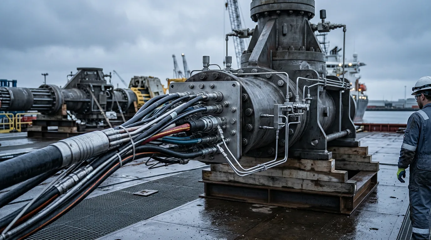
- Umbilical hydraulics. Long umbilical injection lines lose a lot of pressure and take a long time to transit. Size tubes for the highest-viscosity fluid at the lowest temperature, and calculate how long fresh chemical takes to reach the injection point at the lowest planned dose rate. A line sized only for maximum flow can leave dead volumes that take ages to flush.
- Fluid compatibility. Inhibitors, corrosion inhibitors, scale inhibitors and wax or asphaltene treatments have to be compatible with each other, with the umbilical materials and with the produced fluids. Qualification should include cold-temperature viscosity and stability testing.
- Injection point selection. Put injection where it protects the most vulnerable parts of the system: downhole, at the tree and at the manifold. Provide redundancy wherever a single blocked line would stop production.
- Metering and verification. Subsea metering has to be verifiable. A dose rate you can't confirm is not a barrier.
- Host capacity. Storage, pumps, MEG regeneration or methanol handling, and discharge limits at the host are often the real constraint. A tieback that fits the host's process system but not its chemical systems doesn't fit.
Illustrative scenario
This is a constructed example for guidance. It is not a real project or a sizing calculation.
An oil tieback is planned to an ageing host. At first production, the flowline runs warm and the thermal margin looks comfortable. The design basis, however, includes a late-life case with lower rates and high water cut. Reviewing that case shows arrival temperature falling toward the hydrate region, and the cooldown time after shutdown shrinking below the time the host needs to arrange a flush of the line.
The team has three options. The first is to add insulation. The second is to add heating to the flowline. The third is to accept a shorter cooldown and rely on hydrate inhibitor injection from the host. Their review finds that:
- Added insulation helps, but it doesn't remove the need for a shutdown procedure.
- Active heating addresses the limiting case, but it needs power and subsea electrical reliability the host can't easily support.
- Chemical injection works only if the umbilical can deliver inhibitor to the tree within the available cooldown time. The existing umbilical design has a long transit time at low dose rates.
The decision is to combine improved insulation with a redesigned injection line and a defined shutdown procedure, and to record the late-life case as the controlling scenario in the flow assurance basis. The lesson is in the sequence: define the limiting case, test each barrier against it, and only then set operating procedures.
Practical checklist
- Is the controlling design case the late-life, low-rate, high-water-cut shutdown rather than the plateau case?
- Does the flow assurance basis state the allowable cooldown time and the action required when it is reached?
- Can the host physically execute displacement, depressurisation and restart, including pumps, routes and fluid disposal?
- Does the umbilical injection line deliver chemical to the injection point within the time the design requires, at the lowest planned dose rate?
- Have all injected chemicals been tested for compatibility with each other, the umbilical materials and the produced fluids at cold conditions?
- Is there redundancy for injection lines serving the most critical points?
- Can dose rates be verified at the point of injection?
- Does the host have chemical storage, pumping and regeneration or discharge capacity for the full field life?
- Has active heating been evaluated against its power, connector and reliability requirements?
- Is there a written, safety-reviewed plug remediation procedure covering isolation, depressurisation, verification of zero energy, LOTO, gas detection and safe venting?
- Have operations staff reviewed and accepted the shutdown and restart procedures before first production?
Conclusion
Long tiebacks fail on the transients the design basis treated as secondary. Find the limiting case, usually a late-life shutdown, and test insulation, heating and chemical injection against it together. Then confirm the host can actually carry out the procedures that follow. Before sanction, have the operations team challenge the flow assurance basis, check the umbilical's response time against the cooldown time, and confirm host chemical capacity for the full field life. Hold the shutdown, restart and remediation procedures to the same review standard as the hardware.